


TI engineers:
Hello.
I have some problems about TX Phase Shifter Calibration.
I calibrate according to the manual, the calibration process is as follows:
first:
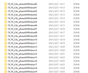
run Cascade_Phase_Shifter_Calibration_AWRx.lua to get datasheet:
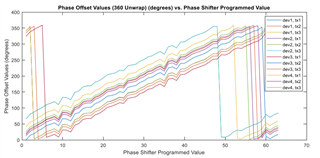
Second step, I run the cascade_TX_Phase_Calibration.m to get calibrateTXPhaseResults.mat

But the graphic display is different: (a) is the result of my running and (b) is the result of the manual.
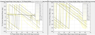
(a)
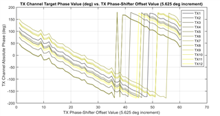
(b)
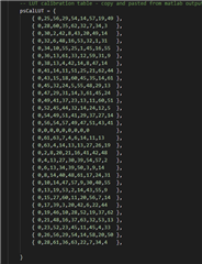
third step: I run TXBF_PS_LUT_Generate.m and get two .csv document

But the graphic display is different: (a) is the result of my running and (b) is the result of the manual.
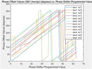
(a)
(b)
the fourth step: Update the calibration matrix in psSettingProgramCal.csv to Cascade_Configuration_TXBF_AngleSweep.lua
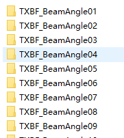
the five step . in the same enviroment ,run the Cascade_Configuration_TXBF_AngleSweep.lua get 31 document
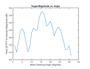
the six step run the cascade_TXBF_Verification.m
But the graphic display is different: (a) is the result of my running and (b) is the result of the manual.
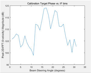
(a)
(b)
my question are:
1、 Since the second step, my results have been different, and the final results are also not correct. What is the cause of this?
2、In the above process, is there any step I am incorrect or missing?
3、This is my experimental environment. Is there any problem?
...
