This thread has been locked.

If you have a related question, please click the "Ask a related question" button in the top right corner. The newly created question will be automatically linked to this question.

IWR6843ISK-ODS: How to configure uart's baud rate to 1843000 /3125000 on IWR6843 ES2.0

Part Number: IWR6843ISK-ODS
Other Parts Discussed in Thread: IWR6843

Dear TI Expert

Platform : IWR6843ES2.0 

SDK version: 3.4.03

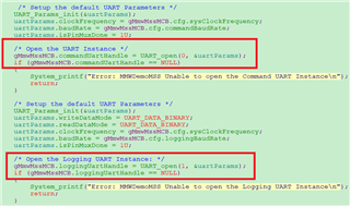
According mmwave sdk user guide instructions, uart baudrate can support 1843200, 3125000 bps.

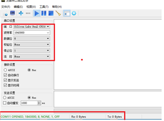
We modified source code and set baud rate to 18432000 or 3125000,  Setting the same baud rate(18432000/3125000) on the PC side cannot receive uart data.

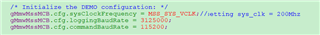
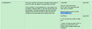
So my question is :how to configure uart's baud rate to 1843000 or 3125000? Please provide a detailed description,thanks!

We use mmwave demo visualizer tool to configure rader and set uart baud rate to 1843000 or 3125000,the radar waveform is also not displayed.


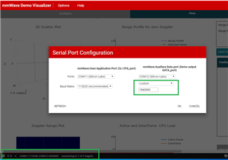
We do not know how to configure the maximum baud rate, please help to solve it, thank you.

  • Hello,

    Your code changes on the target side look correct. Instead of the mmWaveDemoVisualizer, could you try connecting a terminal utility such as Tera term or Putty to the data UART port with the higher baud rate and see if it shows the data stream coming out? Note that the data stream will not be readable as it is coming out as binary data and not ascii text, but this will at least tell us if the mmw demo is sending some output at all with the higher data UART rate or not.

    Thanks

    -Nitin 

  • Hello Nitin

    We tested 1843000 and 3125000 baud rates with the serial port debugging tool or Python APP, but we still did not receive the data sent by UART. If the baud rate is set to 921600 BPS, we can receive the data from UART, so please confirm the maximum supported baud rate, thank you.

  • Hello,

    I can confirm that the 6843 ES2.0 support the 3.125Mbps UART. also, it only work with XDS110 emulator, the on board USB-UART brige SI2105 only support 921600kbps. So, please confirm that the data is send out through the UART interface. Then, please check the brige chip and PC GUI also support this baudrate. 

    Thanks.

    Regards,

    Wesley

  • Hello Wesley

    Thanks for your information.

    We use cp2105 usb-to-dual uart bridge, Standard UART  baudrate max is 9216000 bps, enhanced UART baud rate is 300 bps to 2.0 Mbps.

    As you know iwr6843 demo code default UART(SCI) Logging Baud Rate is set to 921600, UART(ECI) Command Baud Rate is set to 115200, if we swap these two uart baud rates, is this ok?

  • Hi,

    It should be OK. you can do a quickly test with set the command UART port to <2Mbps baudrate.

    Thanks.

  • Hi,

    My modifications are as follows, please help to confirm.

    /* Initialize the DEMO configuration: */
    gMmwMssMCB.cfg.sysClockFrequency = MSS_SYS_VCLK;//setting sys_clk = 200Mhz
    gMmwMssMCB.cfg.loggingBaudRate = 921600;
    //gMmwMssMCB.cfg.commandBaudRate = 115200;
    gMmwMssMCB.cfg.commandBaudRate = 1843000;

    By the way,does MSS_SYS_VCLK need to be modified, if yes,how do you configure VCLK,thanks!

  • Hi,

    You dont need to change the VCLK, what you need to do is only change the 115200 to xx you want.

    You can find more details inTRM. https://www.ti.com.cn/cn/lit/pdf/swru522

    Regards,

    Wesley

  • Hello Wesley

    I have another question to confirm: 

    The  schematic diagram RADAR_MSS_LOGGER(PAD F14) is connected to RXD_SCI of CP2105 ,USB_AR_rs232_TX (PAD N5)is connected to RXD_ECI, and USB_AR_rs232_RX (PAD N4)is connected to TXD_ECI .

    According to the instructions of CP2105, only Enhanced UART's bauder rate can support 2Mbps, so we need to connect RADAR_MSS_LOGGER to RXD_ECI. Currently, there is no way to modify the hardware. How to modify the software so that the baud rate of RADAR_MSS_LOGGER can support 2Mbps. 

  • Hi ,

    You dont need to swap these pin in Hardware, Please do it in software.

    You can use single N4N5 uart for all the things. and it support 2Mbps on ISK board

    What you need to do is modify the communication protocol code by youself.

    And, current demo and sdk driver only use MSS_LOGGER UART's TX pin, if you want to use this to receive something from PC, you need to modify the SDK driver and pinmux. 

    Thanks.

    Regards.

    Wesley

  • Hello

    mss_mian.c: UART_open() first parameter index(0,1,2..), How do you configure it?

    IWR6843 has MSS_UART_A, MSS_UART_B, BSS_UART, and DSS_UART. What are their corresponding indexes?

  • Hello

    uart_open(0)  ==> open MSS_SCI_A

    uart_open(1) ==> open MSS_SCI_B

    Is this correct or not?

  • Hi,

    You goes in wrong direction. Please follow below step.

    1. modify the baudrate for commandBaudRate, then you can get 921600bps in N4N5 port.

    /* Initialize the DEMO configuration: */
    config->sysClockFrequency = MSS_SYS_VCLK;
    config->loggingBaudRate = 921600;
    config->commandBaudRate = 921600;//115200;

    2. find all the UART_writePolling  in mss_main.c file, and replace the uartHandle from "gMmwMssMCB.loggingUartHandle" to "gMmwMssMCB.commandUartHandle", then you can get the points cloud and other tracking data output from N4N5 pin.

    UART_writePolling (uartHandle,
    (uint8_t*)&tl[tlvIdx],
    sizeof(MmwDemo_output_message_tl));

    3. To make sure your GUI can get correct binary data, you also need to modify the UART mode

     uartParams.writeDataMode = UART_DATA_BINARY;

        uartParams.readDataMode = UART_DATA_BINARY;

    4. make sure your GUI communication protocol on your GUI code is modified by yourself to match the new communication protocol and data format.

    With step 1, you can get 921600bps in N4N5 port, with step 2, you can get detected points from same port(by this way, you only need N4N5 port, and the MSS_LOGGER_PORT is not required anymore). It depends on how you use it, you can use only one UART or keep 2 UART port.

    Step 3 and 4 should be done by yourself, TI didnot have any reference code for this kind of application. But it's alredy evaluated by multiple customers.

    Regards,

    Wesley

  • Hello Wesley

    Thank you very much for your great support !

     If we modify the baudrate to 2M bps  for commandBaudRate , Besides baud rate, is there anything else that needs to be modified for IWR6843?

    /* Initialize the DEMO configuration: */
    config->sysClockFrequency = MSS_SYS_VCLK;
    config->loggingBaudRate = 921600;
    config->commandBaudRate = 2000000;//115200;

  • Hi,

    No other steps you need to do.

    But you need to take a look at the Actual Baud Rate

    Actual Baud Rate = 200MHz / (16*(SCI_BAUD+1))

    When SCI_BAUD = 5, you can get 2083333 bps at UART. when SCI_BAUD = 6, you get 1785714 bps, so you can not get exactly 2Mbps due to the UART IP limitation.

    So, i recommend you try 1785714 bps in both IWR6843 and GUI side.

    You can find more details inTRM. https://www.ti.com.cn/cn/lit/pdf/swru522

    Thanks.

    Regards,

    Wesley

  • Hello

    Do you mean that SCI_BAUD does not need to be configured via software?

    In uartscl.c:: UartSci_open this function:

    Currently, the commandBaudRate rate is set to 1843000, both sending and receiving data are correct.

  • Hi,

    You dont need to take care about the SCI_BAUD if everything works fine.

    Please take a look at SCI_BAUD setting once you found the baudrate not match your expection in someday.

    Thanks.

  • Hello

    ok , i see.

    Thanks a lot again!

  • Hello

     if config uartParams.baudRate   = 1843200  or   uartParams.baudRate   = 1920000 ,When receiving uart data, it was found that there was a bit loss problem. I guess it may be related to the data sent by uart.
    Please give some suggestions to help us verify the problem, thank you.


  • Hi User this thread is now closed. Please open up a new one.

    Regards,

    AG