This thread has been locked.

If you have a related question, please click the "Ask a related question" button in the top right corner. The newly created question will be automatically linked to this question.

IWR6843ISK-ODS: Missing data straight ahead of sensor

Part Number: IWR6843ISK-ODS
Other Parts Discussed in Thread: IWR6843, IWR6843AOP,

Hi, I am looking at IWR6843 isk-ods using the ROS diver.

I am on a moving platform and I have noticed the following: Detection are rear stright infront of the sensor. Even when I put reflectors there.

The picture shows all detections from a run during 1 min.

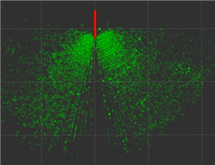
Question 1: Why is this? The lobe of the antenna is the strongest here and the angular resolution should be the smallest.Is there a physical explanation or how to fix this? or is it boundry effects in fft?

Question 2: I have noticed that ROS does not have IWR6843ISK-ODS cfg. We will evaluate IWR6843AOP, Will this be present there as well?

Setup:

I have flashed the ODS with the pointclould binary from the 3.5 version of the SDK.

I have tried the default 6843AOP_3d cfg also I have modified it to look like:

% ***************************************************************
% Created for SDK ver:03.05
% Created using Visualizer ver:3.5.0.0
% Frequency:60
% Platform:xWR68xx_AOP
% Scene Classifier:best_range_res
% Azimuth Resolution(deg):30 + 30
% Range Resolution(m):0.047
% Maximum unambiguous Range(m):2.41
% Maximum Radial Velocity(m/s):0.81
% Radial velocity resolution(m/s):0.11
% Frame Duration(msec):50
% RF calibration data:None
% ***************************************************************
sensorStop
flushCfg
dfeDataOutputMode 1
channelCfg 15 7 0
adcCfg 2 1
adcbufCfg -1 0 1 1 1
profileCfg 0 60 474 7 40 0 0 100 1 64 2000 0 0 158
chirpCfg 0 0 0 0 0 0 0 1
chirpCfg 1 1 0 0 0 0 0 2
chirpCfg 2 2 0 0 0 0 0 4
frameCfg 0 2 16 0 50 1 0
lowPower 0 0
guiMonitor -1 1 0 0 0 0 1
cfarCfg -1 0 2 8 4 3 0 11 0
cfarCfg -1 1 0 4 2 3 1 15 1
multiObjBeamForming -1 1 0.5
clutterRemoval -1 0
calibDcRangeSig -1 0 -5 8 256
extendedMaxVelocity -1 0
lvdsStreamCfg -1 0 0 0
compRangeBiasAndRxChanPhase 0.0 1 0 -1 0 1 0 -1 0 1 0 -1 0 1 0 -1 0 1 0 -1 0 1 0 -1 0
measureRangeBiasAndRxChanPhase 0 1.5 0.2
CQRxSatMonitor 0 3 4 99 0
CQSigImgMonitor 0 31 4
analogMonitor 0 0
aoaFovCfg -1 -90 90 0 90
cfarFovCfg -1 0 0 2.40
cfarFovCfg -1 1 -0.81 0.81
calibData 0 0 0
sensorStart

I use the launch file:

<arg name="max_allowed_elevation_angle_deg" default="90" doc="Maximum allowed elevation angle in degrees for detected object data [0 > value >= 90]}"/>
<arg name="max_allowed_azimuth_angle_deg" default="90" doc="Maximum allowed azimuth angle in degrees for detected object data [0 > value >= 90]}"/>

Best regards

  • Hello,

    Thank you for collecting this data. Answering your questions in order:

    1. The image clearly shows fewer points at boresight. I will take an action to discuss this internally and post back to you. If you have a ISK (non-ODS), could you re-do the experiment to show the differences? The ODS board was designed to have a wider field-of-view compared to ISK.

    2. Yes, we do not have a CFG specific to the ODS, as we have seen more demand for ISK and AOP.

  • Hi, No I do not have the isk antenna but I can see from promotion videos its not present. Perhaps it is present but due to better resolution in azimuth its clearly visable. Please hava a look, it is quite clear. My question is why and more importantly, is this effect present on the AOP? 
    looking at,
    https://training.ti.com/360-degree-safety-bubble-robotics-using-ti-mmwave-sensors

    seems to work, but I guess you know this? 
    best regards

  • The effect has not been noticed on AOP with your test procedure. This would have been caught when measuring radiation patterns: https://dev.ti.com/tirex/explore/node?node=AGMzFzzFdFllMlyaWeXNlw__VLyFKFf__LATEST&r=VLyFKFf__2.1.2&r=VLyFKFf__2.5.2&r=VLyFKFf__3.0.0&r=VLyFKFf__3.6.2&r=VLyFKFf__4.0.0

    Could you please document your exact test procedure with ROS commands and all? Please provide images of your setup as well if you are able. The more detailed the better.

    Furthermore, I would suggest you have a look at the Range Bias and Rx Channel Gain/Phase Measurement and Compensation provided in the mmWave SDK? This may address this issue. 

  • Hi.

    My setup:

    I flashed with:

    Now I launched the launch file cfg file 6843AOP_multi_3d_0.cfg in ROS. The above cfg is slightly modified but neither works.

    My card is during run:

    The setup is, I have coke can with coke in it at 80 cm and I rotate the sensor.

    The can is where my mouse is. In case if the video does not work, here are some screenshots

    I tried to do Range Bias and Rx Channel Gain/Phase Measurement and Compensation.

    Best regards.

  • Hi Amir,

    Thank you for posting back, this is helpful. I was referring to the first image you posted, where you run the device for 1 min. Could you post some steps for that?

    Did your tests improve after doing the calibration steps?

  • The first test is the same setting but I plot all points during 1 min. So if you want to reproduce, launch the ROS driver.

    1) Choose your radar frame in rviz

    2) Set Decay time in pointcloud2 massege to a huge number, 5000 sec. 

    3) Collect the points (preferably indoors) by constantly moving and rotating the radar towards various objects. The longer time you do this the more visible it is.

    It is actually even more visible by doing:

    Point radar towards an object with free space around it, and rotate the radar. You will then see all points on a circle with distance X but detections are weak and few straight ahead. This is the last video/images I sent.

    No as shown above, the calibration failed. What am I doing wrong?

    The procedure was, plug in USB cable, go to Plots and load the config shown in the image. Launching a "run time" config works.

    Best regards.

  • Thanks Amir,

    Do you have a transform publisher when rotating the radar? This would put the point cloud into the correct locations and is necessary when radar is moving.

  • Yes I hava the static transform in your launch file 6843AOP_multi_3d_0, otherwise its not possible to view in rviz.But the entire point is that the frame is static and you rotate the radar, then you see it relative to the radarframe, in this particular frame we see that we cannot see straight ahead objects. This setup is equivalent to your demo visualizer, where it is not possible to see the issue due to low resolution plot.

    Again, why do the calibration fail with bpmcfg not supported?


  • bpmCfg is a newer command, are you sure you are using the latest SDK and demo visualizer version?

  • I am using 3.5 in the demo visualizer.

    Have a look at the binary I loaded (Img posted earlier). It is named xwr64xxODS not xwr68xxODS. It is taken from the industrial toolbox 4-5-1. I suppose this is correct?

    I use profile_calibration in mmwave_sdk_03_05_00_04. Again you can see the path in the image provided.

    I guess i need to either reflash firmware with another binary from industrial toolbox or change profile_calibration from previous mmwave_sdk?

    What versions correspond to what binary?

    Best regards

  • I can verify that you are using the correct firmware version. Yes it is a little confusing, mmWave SDK 3.5 is used in Industrial toolbox 4.5.1 and later.

    Just want to confirm that you are using this version of mmWave studio. Note that it specifies 3.5 in the URL.

  • yes, I can verify this since I generated the cfg from there.

    % ***************************************************************
    % Created for SDK ver:03.05
    % Created using Visualizer ver:3.5.0.0
    % Frequency:60
    % Platform:xWR68xx_AOP
    % Scene Classifier:best_range_res
    % Azimuth Resolution(deg):30 + 30
    % Range Resolution(m):0.047
    % Maximum unambiguous Range(m):2.41
    % Maximum Radial Velocity(m/s):0.81
    % Radial velocity resolution(m/s):0.11
    % Frame Duration(msec):50
    % RF calibration data:None
    % ***************************************************************
    sensorStop
    flushCfg
    dfeDataOutputMode 1
    channelCfg 15 7 0
    adcCfg 2 1
    adcbufCfg -1 0 1 1 1
    profileCfg 0 60 474 7 40 0 0 100 1 64 2000 0 0 158
    chirpCfg 0 0 0 0 0 0 0 1
    chirpCfg 1 1 0 0 0 0 0 2
    chirpCfg 2 2 0 0 0 0 0 4
    frameCfg 0 2 16 0 50 1 0
    lowPower 0 0
    guiMonitor -1 1 0 0 0 0 1
    cfarCfg -1 0 2 8 4 3 0 11 0
    cfarCfg -1 1 0 4 2 3 1 15 1
    multiObjBeamForming -1 1 0.5
    clutterRemoval -1 0
    %calibDcRangeSig -1 0 -5 8 256
    calibDcRangeSig -1 1 -5 8 256
    extendedMaxVelocity -1 0
    lvdsStreamCfg -1 0 0 0
    compRangeBiasAndRxChanPhase 0.0 1 0 -1 0 1 0 -1 0 1 0 -1 0 1 0 -1 0 1 0 -1 0 1 0 -1 0
    measureRangeBiasAndRxChanPhase 0 1.5 0.2
    CQRxSatMonitor 0 3 4 99 0
    CQSigImgMonitor 0 31 4
    analogMonitor 0 0
    aoaFovCfg -1 -90 90 0 90
    cfarFovCfg -1 0 0 2.40
    cfarFovCfg -1 1 -0.81 0.81
    calibData 0 0 0
    sensorStart
  • Hi Amir,

    I am now understanding what your problem is. bpmCfg is failing because you have used incorrect profile_calibration.cfg.

    You used profile_calibration.cfg from 68xx directory. You need to use from 64xx directory.

  • Thanks, I will try flash and get back to you

  • Hi, I did the calibration and it did the trick.

    Now I get weaker signatures on the sides, as expected.

    So I find a hint on whats wrong:

    If you run ODS on AOP config in ROS, you will note that the axis are flipped in a quite strange manner:

    I added this to get it right:

    if (RScan->points[i].y <= 0 && RScan->points[i].x <= 0)
    {
    // RScan->points[i].x = -RScan->points[i].x;
    // RScan->points[i].y = -RScan->points[i].y;
    }

    But after calibration this should be removed. The code above does not remove any points so its not a cause of the issue. But the "calibration" did not just adjust a couple of degrees, it change the entire frame. I noticed this in the demo visualizer as well.

    As I mentioned, we will try out the AOP.

    Best regards and thank you.

  • Glad to hear you were able to find success.