This thread has been locked.

If you have a related question, please click the "Ask a related question" button in the top right corner. The newly created question will be automatically linked to this question.

AWR1843BOOST: Zero ADC Sample Value Over 4 Channels in 3Tx&4Rx Configuration

Part Number: AWR1843BOOST
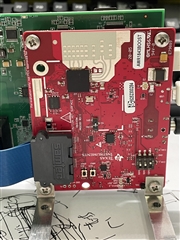
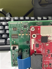
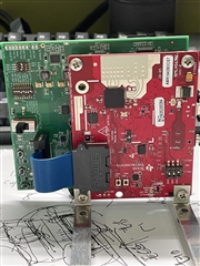
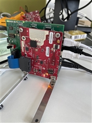
Other Parts Discussed in Thread: DCA1000EVM, AWR1843

Hi Expert,

We have a data capture problem in the using of AWR1843 + DCA1000EVM. To be specific, when we set the 3TX&4RX mode in AWR1843, the data we received had zero ADC value over 4 channels. There was no such problem in 2TX&4RX mode. We verified this issue in UDP packet analysis. The sequence number of raw data in every UDP packet is consecutive and the number of total data bytes meet our radar configuration. But there were zero ADC data values over 4 channels of UDP packets.

And we also find no matter how we set the frame number of the capture configuration, the actual capture process ended with in 70~80 seconds.

We put the LUA command of our initialization as following. Could you please help us to check whether there are some miss configuration cause these problems.

---------------------------------- STARTUP -------------------------------------
------------------------ DO NOT MODIFY THIS SECTION ----------------------------

-- mmwavestudio installation path
--RSTD_PATH = RSTD.GetRstdPath()

-- Declare the loading function
--dofile(RSTD_PATH .. "\\Scripts\\Startup.lua")

------------------------------ CONFIGURATIONS ----------------------------------
-- Use "DCA1000" for working with DCA1000
capture_device  = "DCA1000"

-- SOP mode
SOP_mode        = 2

-- RS232 connection baud rate
baudrate        = 115200
-- RS232 COM Port number
uart_com_port   = 4
-- Timeout in ms
timeout         = 1000

--system_ip = "192.168.33.30"
--fpga_ip = "192.168.33.180"

-- BSS firmware
bss_path        = "C:\\ti\\mmwave_studio_02_01_01_00\\rf_eval_firmware\\radarss\\xwr18xx_radarss.bin"
-- MSS firmware
mss_path        = "C:\\ti\\mmwave_studio_02_01_01_00\\rf_eval_firmware\\masterss\\xwr18xx_masterss.bin"

--adc_data_path   = "C:\\ti\\mmwave_studio_02_01_01_00\\mmWaveStudio\\PostProc\\test_data.bin"


-- Profile configuration
local profile_indx              =   0
local start_freq                =   77     -- GHz
local slope                     =   79     -- MHz/us
local idle_time                 =   25      -- us
local adc_start_time            =   6      -- us
local adc_samples               =   256    -- Number of samples per chirp
local sample_freq               =   10000   -- ksps
local ramp_end_time             =   40     -- us
local rx_gain                   =   48     -- dB
local tx0OutPowerBackoffCode    =   0
local tx1OutPowerBackoffCode    =   0
local tx2OutPowerBackoffCode    =   0
local tx0PhaseShifter           =   0
local tx1PhaseShifter           =   0
local tx2PhaseShifter           =   0
local txStartTimeUSec           =   0
local hpfCornerFreq1            =   0      -- 0: 175KHz, 1: 235KHz, 2: 350KHz, 3: 700KHz
local hpfCornerFreq2            =   0      -- 0: 350KHz, 1: 700KHz, 2: 1.4MHz, 3: 2.8MHz

-- Frame configuration    
local start_chirp_tx            =   0
local end_chirp_tx              =   2
--local nchirp_loops              =   128     -- Number of chirps per frame
local nchirp_loops              =   1     -- Number of chirps per frame
--local nframes_master            =   100     -- Number of Frames for Master
local nframes_master            =   100000     -- Number of Frames for Master
local nframes_slave             =   10     -- Number of Frames for Slaves
--local Inter_Frame_Interval      =   100    -- ms
local Inter_Frame_Interval      =   20    -- ms
local trigger_delay             =   0      -- us
local trig_list                 =   {1,2,2,2-- 1: Software trigger, 2: Hardware trigger    

------------------------- Connect Tab settings ---------------------------------
-- Select Capture device
ret=ar1.SelectCaptureDevice(capture_device)
if(ret~=0)
then
    print("******* Wrong Capture device *******")
    return
end

-- SOP mode
ret=ar1.SOPControl(SOP_mode)
RSTD.Sleep(timeout)
if(ret~=0)
then
    print("******* SOP FAIL *******")
    return
end

-- RS232 Connect
ret=ar1.Connect(uart_com_port,baudrate,timeout)
RSTD.Sleep(timeout)
if(ret~=0)
then
    print("******* Connect FAIL *******")
    return
end

ar1.Calling_IsConnected()
--ar1.SelectChipVersion("AR1642")
ar1.SelectChipVersion("XWR1843")

-- Download BSS Firmware
ret=ar1.DownloadBSSFw(bss_path)
RSTD.Sleep(2*timeout)
if(ret~=0)
then
    print("******* BSS Load FAIL *******")
    return
end

-- Download MSS Firmware
ret=ar1.DownloadMSSFw(mss_path)
RSTD.Sleep(2*timeout)
if(ret~=0)
then
    print("******* MSS Load FAIL *******")
    return
end

-- SPI Connect
ar1.PowerOn(0100000)

-- RF Power UP
ar1.RfEnable()

------------------------- Other Device Configuration ---------------------------

-- ADD Device Configuration here

ar1.ChanNAdcConfig(1111111220)
ar1.RfLdoBypassConfig(0x3)
ar1.LPModConfig(01)

ar1.RfInit()
RSTD.Sleep(1000)


ar1.DataPathConfig(51312166440970)

--ar1.DataPathConfig(1, 1, 0)

ar1.LvdsClkConfig(11)

ar1.LVDSLaneConfig(01100100)

                  
--ar1.ProfileConfig(0, 77, 100, 6, 60, 0, 0, 0, 0, 0, 0, 29.982, 0, 256, 10000, 0, 0, 30)
ar1.ProfileConfig(0start_freqidle_timeadc_start_timeramp_end_time000000slope0adc_samplessample_freq00rx_gain)


-- Chirp 0
ar1.ChirpConfig(0000000100)


-- Chirp 1
ar1.ChirpConfig(1100000001)


-- Chirp 2
ar1.ChirpConfig(2200000010)


ar1.DisableTestSource(0)

--ar1.EnableTestSource(1)

ar1.FrameConfig(start_chirp_txend_chirp_txnframes_masternchirp_loopsInter_Frame_Interval001)
--ar1.FrameConfig(0, 0, 8, 128, 40, 0, 0, 1)


ar1.CaptureCardConfig_EthInit("192.168.33.30""192.168.33.180""12:34:56:78:90:12"40964011)

ar1.CaptureCardConfig_Mode(1212330)

ar1.CaptureCardConfig_PacketDelay(5)
capture_time = 100000

--data_folder_path = "C:\\ti\\mmwave_studio_02_01_01_00\\mmWaveStudio\\PostProc\\"
data_folder_path = "D:\\data\\"
data_file_name = "adc_data.bin"

adc_data_path   = data_folder_path  ..data_file_name
--adc_data_path   = "C:\\ti\\mmwave_studio_02_01_01_00\\mmWaveStudio\\PostProc\\test_data2.bin"
jsonFilePath_Capture = data_folder_path  .."AWR1843.setup.json"
jsonFilePath_mmwave = data_folder_path .."AWR1843.mmwave.json"
--Start Record ADC data
ar1.CaptureCardConfig_StartRecord(adc_data_path1)
RSTD.Sleep(1000)

--Trigger frame
ar1.StartFrame()
RSTD.Sleep(capture_time)

--Post process the Capture RAW ADC data
--ar1.StartMatlabPostProc(adc_data_path)
--WriteToLog("Please wait for a few seconds for matlab post processing .....!!!! \n", "green")
--RSTD.Sleep(10000)

ar1.JsonExport(jsonFilePath_Capture,jsonFilePath_mmwave)
  • Please give our team some time to review your configuration

    thank you

    Cesar

  • Can you provide a few pictures of your physical setup? This will help in identifying the issue.

    Regards,

    Kyle

  • Hey Kyle,

    Thanks for your timely reply. Are this images clear for you ?

    Regards,

    Jinbo

  • Jinbo,

    Thank you for your reply. Let me review your images and get back to you.

    Regards,

    Kyle

  • Jinbo,

    Are you able to run the capture demo LUA script that is included in the mmWave Studio installation on your AWR1843 device? Does this script raise any error messages?

    Regards,
    Kyle

  • I did not see the Ethernet cable in your physical connection images. Perhaps I missed it but I was not able to find it in your images. Please make sure to manually set the IPv4 address on your PC to 192.168.33.30.

    Additionally, please make sure your power supply is rated for 5V and at least 3A.

    Regards,

    Kyle

  • Hey Kyle,

    The script  I post works well if I choose the 2TX 4RX mode by modified the 'ar1.FrameConfig'. We have tried many tests recent days, There are something new might help u to check.

    1.   'inter frame interval' is the key parameter in this problem. When we set the inter-frame-interval = 20ms, both 2TX&4RX mode and 3TX&4Rx mode work well. But when we set it to 100ms, only 2TX&4RX mode works well. 3TX&4RX mode in 10ms inter-frame-interval config leads to packet  lose. We check the received UDP packet and found that almost 4 channels of raw ADC samples lost.  We check the DCA1000's theoretical throughput limitation on the user guide. It  says that DCA1000 has ~706 Mbps theoretical throughput  when ethernet packet delay is 5 us. We believe the actual throughput in our config is far less than 706 Mbps.

    2. We also tried to modify the config to have a longer capture time, but those effort all failed. No matter how we modify the config (frame number, inter-frame-interval), the actual capture process will ended in about 80 seconds. Is there any hardware limitation cause this problem?


    Thanks!

    Regards,

    Jinbo

  • Jinbo,

    Please allow me some time to review all of this information and I will get back to you next week.

    In the meantime, the reason your actual capture takes so long is due to this line:

    RSTD.Sleep(capture_time)

    Earlier in the script, you define the variable capture_time as 100,000. The RSTD.Sleep function accepts values with 1 LSB equaling 1 ms. So RSTD.Sleep(1000) would equate to a 1 second delay. So in your case, you are inserting a fixed 100 second delay in your script that is independent of any of the profile/chirp/frame configurations. This is not a hardware limitation as suggested in question #2 but rather the proper execution of your script given the parameter passed into the RSTD.Sleep function.

    With regards to the DCA1000 throughput, what is the clock rate you are specifying in your LUA script for LVDS?

    Regards,

    Kyle

  • Hi Kyle,

    Maybe I miss represented my problem.   'RSTD.Sleep(capture_time)'  is just a sleep delay time to let us receive the complete data to do the MATLAB post process  for debug purpose. In our case, we set the capture time equals to 100000  simply because  the actual time of awr1843 capture process will no longer greater than 80 seconds. So our problem is we don't know how to have a longer data capture time ( > 80 s) . Take 3 minutes for example, since the inter frame  interval in our config is 10ms, we set the number of frames equals to 18000. However the capture will be ended with in 80 seconds (we only received around 8000 frames of raw data). 

    As for clock rate, we set it to 600MHZ DDR clock. 

    Also, I find there was a typing problem. Let me correct it : ) 

    ' But when we set it to 10ms, only 2TX&4RX mode works well. 3TX&4RX mode in 10ms inter-frame-interval config leads to packet  lose'

    Thanks!

    Regards,

    Jinbo

  • Jinbo,

    Based on your profile configuration, a 10 ms frame periodicity is too short of a time to complete a a 3 TX configuration. The limitation is not in the number of RX antennas enabled. Please increase your frame periodicity to avoid the dropped packet issue that you are currently seeing.

    A 100 frames per second frame rate is quite fast and would leave little time for any sort of interframe processing. That is why I am suggesting increasing the frame periodicity (which in conjunction decreases the frame rate) to allow for adequate interframe processing.

    Regards,
    Kyle

  • Hi Kyle,

    I understand what you said. I am just curious about the specific reason caused this issue. But the 20ms configuration is fine for my application

    : )

    The capture process time problem really bother me :( 

    I cannot acquire more than 80 seconds raw data every capture process, means  I need to recapture many time to have enough data. How can we have longer capture time in one capture process. Could u please help me with this issue.

    Thanks!

    Jinbo,

    Sincerely

  • Jinbo,

    To have a longer capture time, you need to increase the number of frames in your frameConfig. This will happen by increasing the value of nframe_master.

    The time is takes to complete a capture for a set number of frames is the product of the number of frames and the periodicity of each frame. In the case where nframes_master is 100,000 and the frame periodicity is 20 ms, the total time is takes to complete this capture is 2,000 seconds or 33 minutes and 20 seconds. This is where the RSTD.Sleep(capture_time) line comes into play again. Because you have set it to stop at 100 seconds, you are significantly limiting the amount of data that you are expecting to capture. As I mentioned previously, you will need to increase the capture_time variable in order to capture all of the expected data.

    If you attempt to invoke the postProcessing tool prior to the data capture completing successfully, this will inevitably result in corrupted data.

    A few things to keep in mind going forward:

    1. You need to provide adequate frame periodicity based on your chirp configuration. This is fairly straightforward to calculate. For each profile, take the sum of the idle time and the ramp end time. Multiply this result by the number of chirps associated with this profile. And then finally, multiply this result by the number of chirp loops per frame.

    For example, let's take a chirp profile with an idle time of 10 us and a ramp end time of 40 us. This gives us a total chirp time of 50 us. Then let's say that we implement a TDM-MIMO scenario using all three TX antennas on AWR1843, with each TX transmitting independently. So we would define chirps for each TX antennas, giving us three defined chirps. And finally, we loop through these three chirps 128 times. This would give a total active chirping time of 19.2 ms since (10 us + 40 us) * (3 chirps - 1 per TX) * (128 loops) = 19.2 ms. Based on this result, you would need to specify a frame periodicity of at least 19.2 ms. Typically, TI would recommend having a frame periodicity twice that of the chirp time. So in this particular case, a frame periodicity of 40 ms would work.

    2. When you are attempting to automate the capture of raw data using LUA scripts in mmWave Studio, you need to keep in mind the total length of the frames specified in the frame config. This is found by multiplying the number of frames by the frame periodicity. Using my previous example, and say I want to capture 1,000 frames of raw data, the total capture time would be 40 seconds since (40 ms) * (1,000 frames) = 40 seconds.

    3. Now that you now the expected length of the data capture, you should implement a delay sufficient to accommodate this length. So in the previous example, the expected time to complete the capture is 40 seconds. Giving a 10% overhead to finish ensure the finish of the transfer and mmWave Studio to acknowledge that the data capture has completed successfully, I would implement a delay of 45 seconds before calling the next API in the LUA script.

    All three of this points must be taken into consideration and accounted for when implementing your LUA script. Deviating from any of these will result in incomplete data sets.

    Please review your LUA script given all of this information and make all needed changes.

    Regards,
    Kyle