This thread has been locked.

If you have a related question, please click the "Ask a related question" button in the top right corner. The newly created question will be automatically linked to this question.

HDC2010: HDC2010 never asserts DRDY

Part Number: HDC2010

I'm using the HDC2010 installed on the BASSENSORS Booster Pack, on a Tiva TM4C board.

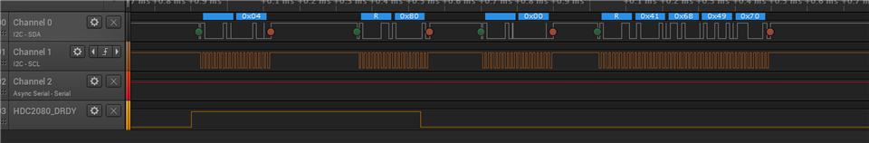
Through I2C I can set and read back all of the 2010's registers. I verified that the manufacturer ID and the part ID numbers are correct, too. I can enable the heater and the part gets warm.

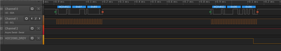
But it doesn't want to actually do the conversion, either triggered with the on-demand mode or auto-measurement mode enabled. DRDY is enabled as an output (bit 2 in register 0xE), INT_MODE is cleared to "level sensitive" (bit 0 in reg 0xE) and the DRDY interrupt is enabled in reg 0x7 bit 7. (No other interrupts are enabled.)

The DRDY pin remains high always. I monitor it with an oscilloscope.

If I change the polarity of the DRDY pin (bit 1 in register 0xE), I see the pin change to the new state. That is, if I change the polarity to active high, the DRDY pin goes low. But it never changes after any conversions, and I can't tell if conversions are actually occurring.

It's a very simple part. What did I miss? Is it just a dead part?

  • Dear Andy - 

    Have you sent the start conversion command? By writing a 0x01 to the part then waiting ~1.3mSec, then looking for the DRDY/INT line to change. 

    Please see this FAQ ==>  https://e2e.ti.com/support/sensors/f/sensors-forum/878721/faq-hdc2080-hdc2010---i-am-getting-incorrect-values-for-example--40c-or-0-rh-or-both-from-hdc-device-for-my-first-read-or-for-any-read-how-to-troubleshoot-the-problem

  • Hi, Josh, 

    I thought the idea behind the auto mode was that I didn't have to do a manual conversion-start. That is, once I set up the automatic mode with whatever rate I selected, it would just do its thing and assert DRDY when a new conversion result was ready. But I never saw DRDY asserted, and reading the interrupt-ready register 0x04 always returned all zeros.

    That said, I set register 0x0E's rate-select bits to use the on-demand trigger, and then sent a trigger with register 0xF, and still never saw DRDY asserted.

  • Dear Andy - 

    The way that works is that once you configure the part, you still need to tell it to start converting one time, to start it. 

    configuring part

    sending the start conversion (just once), getting first IRQ and servicing

    then only IRQs following (zoom)

    overall (showing first and subsequent IRQs, zoomed out)

  • "The way that works is that once you configure the part, you still need to tell it to start converting one time, to start it."

    Ahh, the missing piece of the puzzle -- and I should note, this little detail is not in the data sheet!

    I have the part working well with on-demand triggering, and now that I know what I need to do, I'll update my code.

    One more question: Register 0x0E (Config register) bit 0 is called "INT_MODE" with the description "Interrupt mode" and the options are 0 for "level sensitive" and 1 for "comparator mode." There is no other description of the meaning of these settings. What is "level sensitive" and what is "comparator mode" and why is this description not in the data sheet?

  • Andy - 

    Great! Glad to assist - I agree with you that its not super clear in the datasheet, but only implied in the register bit definition in 0x0F, which makes sense, perhaps only after someone tells you. :) We do have this outlined in the HDC2 Silicon Users Manual User's Manual online - this document is strategically located under the datasheet link on the product page (and link is above, too) - see page 11 for this specific use case. 

    Regarding the interrupt pin behavior when in comparator mode vs. level mode. The diagrams in section 7.3.5 of the datasheet (starts page 11) I think do document the behavior - in looking at Figure 7-3, for example: 

    (top three line diagrams below the temperature graph): In level mode, this pin will assert (high or low, depending on the setting) when threshold is met, however it will not de-assert until register 0x04 is read.   (you would use this mode when needing the IRQ for the MCU/MPU operations...to wake up and be read or just signal that a read is needed, because the limit condition was reached)

    (bottom three line diagrams below the temperature graph): When in comparator mode, this pin will go assert when same threshold is met and de-assert when threshold is not met, on its own. (you would use this mode to control something (fan, compressor, LED, whatever) based on the threshold)

  • Thank you for the detailed explanation, and the HDC2 manual is very helpful, too.

    It's all working now on the test board. Next step is to see how well it works in an actual vacuum chamber.

  • Great, thanks, let us know how it goes!