Other Parts Discussed in Thread: AWR1843
Hello,
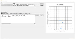
Currently, I am learning the Object Data over CAN (CAN-FD) for xWR1642. I can run the demo like below.

However, I don't quite understand how it works, as it doesn't provide the data parsing example like the other labs using uart. I took a look of the source code and I understood that 0xC1 was for the header, 0xD1 was for the TLV for detected objects. The information of 0xC1 makes sense to me, but I don't know why it magically add 8 bytes of "CC" at the end? The header is 40 bytes for other labs using uart, but for this one it is 48 bytes?
I have three questions about this lab if anyone could help.
(1) How to start the data streaming? From my observation, the xWR1642 didn't start on its own, until we send some commands to it. In the labs using uart, it was achieved by sending "sensorStart" from the command uart port. However, in this lab, we only use a single CAN/CAN-FD port, what command should I send at which ID to start the data streaming?
(2) The data format for the detected object. I was assuming it was the same as the labs using uart. However, it was a little bit difficult for me to decode it without some "data parsing example" for this CAN lab. By any chance, I can get some data parsing examples over the CAN bus?
(3) I think the chirp was hardcode for this lab. However, I could find the chirp/frame configuration file. Where can I find it?
Thank you very much for the help!
Best,
Hang

