This thread has been locked.

If you have a related question, please click the "Ask a related question" button in the top right corner. The newly created question will be automatically linked to this question.

TDC7201: Variable number of STOP pulses

Part Number: TDC7201
Other Parts Discussed in Thread: THS788

Hi Support Team,

I'm using TDC7201 in mode 2. Please answer the following questions:

1. TDC1 is configured for one STOP pulse (and there's always only one), while TDC2 is configured for 5 STOP pulses. However, there are sometimes less than 5 STOP pulses that actually arrive. The maximum meaningful delay time is 10 us. The question is: if I read the registers after a 10 us delay, without waiting for all 5 pulses to arrive, will the readings be correct for those pulses that did arrive within 10 us?

2. If I then (after reading mentioned above) send the start commands to both TDC channels, will they be executed correctly? In other words, will the start command reset the counters if it is issued before the INTBx signal is asserted?

3. What mechanism can you recommend when the number of STOP pulses is not well-defined, but the maximum possible delay is known?

4. The datasheet tells that the minimum delay between two STOP pulses in mode 2 is two clock periods, i.e. 250 ns @8 MHz. Can you suggest a solution for measuring the delays between a single START and multiple STOPs, if the STOPs are separated by a much smaller delay (10 ns and less)?

Thanks in advance,

Michael

  • Hello Michael,

    Thank you for your questions.

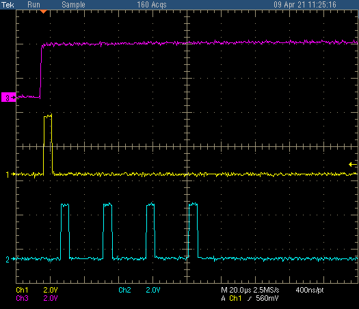
    1. If you attempt to read the registers before you receive the last STOP in a 5 STOP configuration you will not obtain valid results from the registers. As you can see in the image below, I configured the TDC7201 to 5 STOPs but only sent 4 STOPs (blue channel). As you can see INTBx (purple channel) has not toggled again indicating that your measurement is complete and that the data is not available to read in the registers. I believe it would be better to go with an interrupt driven design waiting on INTBx to read the data as soon as its available.

    2. I have not tested this, but sending a new start command before the previous measurement is complete might ignore the command until the measurement is completed or timed out.

    3. If the number of STOPs is not well defined and it is known that the stops are not too close together  it might be better to operate on a single stop configuration, this might use more overhead on the MCU trying to calculate time between STOPs but it is the safest option in order to avoid incorrect data.

    4. For measuring the delays between START and multiple STOPs with that small of a delay would be impossible to do with the TDC7201 device. You would need to find another device that is capable of much faster time measurements. I know some people have asked about the THS788 but have found it too complex it might be worth it to make a generic post for Real-Time Clocks (RTCs) & Timers team to see if they help you find a potential alternative that might be much simpler.

    Best,

    Isaac

  • Hello Isaac,

    thank you very much for such a detailed reply.

    With my current system design, I have the possibility to generate STOP pulses "by hand". The datasheet says that, after the last of the expected STOP pulses has arrived, and before a new start command is issued, the STOP input is insensitive to the incoming pulses, Therefore, my idea is:

    a. Issue a start command.

    b. Wait for a practically meaningful time (10 to 20 us) within which valid STOP pulses can arrive.

    c. Generate 5 STOP pulses "by hand", so that some of them will complete the on-going measurement, and the others will be ignored.

    d. Read the registers as if all 5 STOP pulses were valid, and then sort the measured times of flight using a known criteria (maximum meaningful ToF).

    e. Issue a new start command, and repeat the process.

    Thanks in advance,

    Michael

  • Hello Michael,

    Glad to help out! That is correct once the pulses you are expecting have been received then the system is insensitive to incoming pulses as long as another START is not generated.

    It sounds like this would definitely address the issues you were concerned about if you just take all 5 stop pulses as valid and then used the MCU to calculate the meaningful ToF. The only issue would be if you have any stops within the 250ns then those could possibly be ignored but if you are generating the pulses manually then you could always address this issue to ensure there is enough of a gap between pulses. You could also use mode 1 which has less of a gap of 67ns between STOP pulses.

    Best,

    Isaac

  • Hello Isaac,

    thank you again for your help. Now I'm going to switch to mode 1 to improve resolution, so please answer a few more questions:

    1. The datasheet says that it is not recommended to measure times >2000 ns in mode 1 because of the increased standard deviation. Is this the only reason? I'm asking because, from purely technical viewpoint, the maximal measured time must be about 50 ps * 2^23 = 420 us. Can these long times be measured, if we forget about accuracy? 

    2. I assume that the standard deviation must grow as the square root of the ratio (ToF/55 ps), and Figure 22 really suggests it for ToF < 1000 ns, but then it seems to grow faster than the square root. What is the expected standard deviation for ToF = 20 us in mode 1?

    3. In mode 1, how exactly the TIME1 to TIME6 registers are populated with data in the case of 6 STOP pulses? TIME1 to TIME5 are valid, while TIME6 is not?

    Thanks in advance,

    Michael

  • Hello Michael,

    That is correct if accuracy is what you seek then mode 1 is definitely not the way to go for mesaruments >2000ns. But that seems to be the only reason, the longest ToF I was able to measure using mode 1 was 230us with about a ~100ns standard deviation.

    With a Tof = 20us I am getting ~6ns of standard deviation, currently running it with FORCE_CAL = 0 so calibration is occurring after a measurement is completed.

    There is no setting to set 6 STOP pulses max is 5 pulses, TIME6 register is used for calculations for mode 2 so for mode 1 it will just have 0.

    Best,

    Isaac

  • Hello Isaac,

    thank you very much! Everything is clear now. However, I think there are many applications where measuring 20 us with 6 ns standard deviation will be considered very good. For a LIDAR, this means measuring a 3 km distance with about 1 m standard deviation. Not bad at all ! I would say, this device is greatly underestimated by the suggestion not to use it in mode 1 for ToF > 2 us :-)

    Best regards,

    Michael