This thread has been locked.

If you have a related question, please click the "Ask a related question" button in the top right corner. The newly created question will be automatically linked to this question.

AWR2243: AWR2243 matlab post process results dominated by the cal file rather than the data itself

Part Number: AWR2243

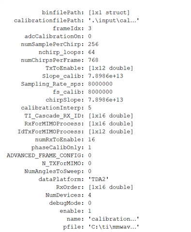
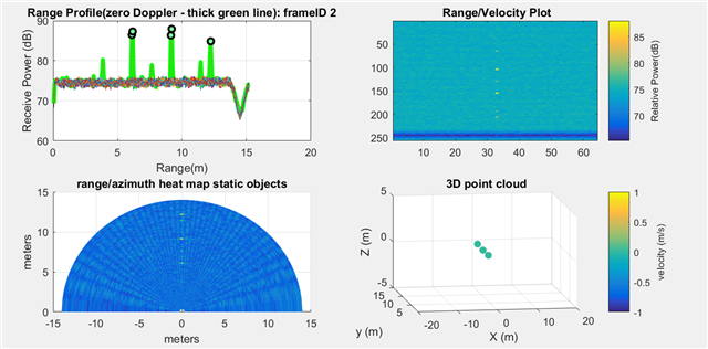
I found weird data process result with AWR2243. Basically I am following mmwave studio 03_00_00_14 MatlabExamples to obtain calibration data and then use the data to generate calibrateResults_high.mat. Then I use cascade_MIMO_signalProcessing.m file to process the data. The problem is: the post results strongly depend on the calibration file, rather than the test data.  Basically, with the same cal data, all post process results almost look the same with no distinguish between different dataset. 

I DID edit the testList.txt file to change cali file to calibrateResults_high.mat and change the dataset directory when I need to switch to new dataset.

Any thoughts?

  • Hi,

    Are you using the cascade kit?

    What about when using without calibration. Does this work?

    Thank you

    Cesar

  • Hello Chen,

    There may be to chip to chip variation due to process and temperature and hence calibration is an important step for cascaded setups. For calibration, you just need to create some sort of a "controlled environment". It is possible if the environment has multiple reflecting elements, and they may mess up the calibration. 

    After calibration of your setup, have you tried experimenting with a strong corner reflector placed at varied ranges from the radar? Were you able to detect those objects at the specified distances? The results should be completely object based. Calibration just helps to provide more accurate estimation data.

    Regards,

    Ishita 

  • Thanks for the details. Our corner reflector was a hand-made one, probably not perfect. We are working on a new corner reflector.  The distance measurement with corner reflector seems messed-up somehow. In the cali script, i typed 5 m as the range estimation and the script told me its estimation at 6.0m.  The actual distance should be around 4-5 m. Then i used cascade_MIMO_signalProcessing.m to process the same data and the plot showed the peak range at 12 m.  It does capture the peak with very good SNR, but the range was not correct. If i turned the cali input file off, the SNR is very low, and the peak is very close to the noise level.  Basically, the postprocess did not capture the corner reflector. 

  • I used mmwave_studio_03_00_00_14 and followed the instruction. If i turned off the calibration (in the adc data decoding script), the peak did not show very well. I am planning to change a corner reflector as the previous one was hand-made.  will post the result if i have some new finding.

  • Hello Chen,

    Thank you for your observations. 

    Can you let us know the process of data capture? Are you using one of our example scripts? What is the configuration used here?

    Have you made sure it's capturing real object data and test source is not enabled? 

    It would be helpful if you could also post a screenshot of your post processed results with your chirp configuration as well. 

    Regards,

    Ishita 

  • Hi, Ishita, thanks for your following up. After several trivials, my original problem statement is not accurate and should be changed to like this: 

    The outputs (processed by cascade_MIMO_signalProcessing.m) were almost the same for the following different inputs:

    1. put the board toward to the sky (1s): Data here: www.dropbox.com/.../sky_04252021.zip

    2. road side with pedestrian and SUV (5s)

    3. corner reflector put at 20ft distance (1s): Data here: www.dropbox.com/.../cr_20ft_04252021.zip

    we used MIMO Configuration for data capture:

    1. Cascade_Configuration_MIMO.lua for configuration of devices  (test_source_enable  =   0      -- 0: Disable, 1: Enable)
    2. Cascade_Capture.lua for capturing data

    Here is calibrationObj info read from matlab workspace

    To remove the impact of calibration, we set calibrationObj.adcCalibrationOn=0. Basically, the process script generated the same plots with above mentioned three dataset.  (if calibrationObj.adcCalibrationOn=1, the conclusion is the same.)

    Output with calibrationObj.adcCalibrationOn=0

    We did compare the raw data and they are similar but apparently different. 

    Let me know if you have any thoughts. Is it HW issue, data collection issue, configuration issue, or data process setting issue?  if you can help process the data mentioned above, and check result difference, it would be appreciated! 

  • Closing this thread since it is a duplicate.