Part Number: LM74
Other Parts Discussed in Thread: MSP430G2553
Dear Sirs,
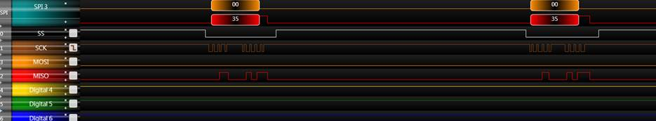
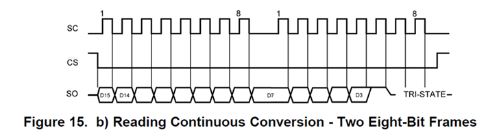
My customer wants to read 2 bytes data with SPI, but found he cannot get data within the same SS period.
The source code also attached.
Please help to review it if there is any problem.
//-----------------------------------------------------------------------------
//
//
//USCIB0 SPI
//                                  MSP430G2xx3
//                               -----------------
//                           /|\|              XIN|-
//                            | |                 |
//                            --|RST          XOUT|-
//                              |                 |
//                              |                 |
//                              |                 |
//                              |             P1.7|-> Data Out (UCB0SIMO)
// Serial Clock Out (UCB0CLK) <-|P1.5         P1.6|<- Data In  (UCB0SOMI)
//                              |                 |
//
//-----------------------------------------------------------------------------
void ConfigSPI_USCIB0(void)
{
	//---------------------------------
	//For USCIB0_SPI
	//---------------------------------
	//
	//	P1.6	UCA0SOMI	SOMI (IN)
	//	P1.7	UCA0SIMO	SIMO (OUT)
	//	P1.5	UCA0CLK		SCLK (OUT)
	P1SEL  |= BIT5 + BIT6 + BIT7;
	P1SEL2 |= BIT5 + BIT6 + BIT7;

	//clock phase		= data is changed on the first UCLK edge, captured on the following edge
	//clock polarity	= active high
	//MSB first select	= MSB first
	//character length	= 8-bit
	//master mode		= master mode
	//USCI mode			= 3-pin SPI
	//synchronous mode	= synchronous mode
	//
	//UCSI clock source	= SMCLK
     UCB0CTL0 |= UCCKPL + UCMSB + UCMST + UCSYNC;	// 3-pin, 8-bit SPI master
	//UCA0CTL0 |= UCCKPH + UCMSB + UCMST + UCSYNC;	// 3-pin, 8-bit SPI master
    UCB0CTL1 |= UCSSEL_2;							// SMCLK

    //bit clock prescaler = 0x0002
    UCB0BR0 |= 0x04;                          // /4
    UCB0BR1 = 0;                              //

    //UCB0MCTL = 0;                             // No baud rate modulation

    //release the software reset (for operation)
    UCB0CTL1 &= ~UCSWRST;                     // **Initialize USCI state machine**
}

unsigned short LM74_ReadRegister(void)
{
    unsigned char HByte;
    unsigned char LByte;
    unsigned short TWord;


    SENSOR_CS_LOW;

    //wait for completion of send
    UCB0TXBUF = 0x00;                   // Transmit the byte
    while (!(IFG2 & UCB0TXIFG));        // USCI_B0 TX buffer ready?
    IFG2 &= ~(UCB0TXIFG);               //clear the interrupt flag

    while (!(IFG2 & UCB0RXIFG));        // USCI_B0 RX Received?
    IFG2 &= ~(UCB0RXIFG);               //clear the interrupt flag
    HByte = UCB0RXBUF;

    UCB0TXBUF = 0x00;                   // Transmit the byte
    while (!(IFG2 & UCB0TXIFG));        // USCI_B0 TX buffer ready?
    IFG2 &= ~(UCB0TXIFG);               //clear the interrupt flag

    while (!(IFG2 & UCB0RXIFG));        // USCI_B0 RX Received?
    IFG2 &= ~(UCB0RXIFG);               //clear the interrupt flag
    LByte = UCB0RXBUF;

    SENSOR_CS_HI;

    TWord = ((HByte<<8)| LByte)>>3;

 //   TWord = TWord>>3;

    return (TWord*0.0625);
}


}
Thanks.