This thread has been locked.

If you have a related question, please click the "Ask a related question" button in the top right corner. The newly created question will be automatically linked to this question.

AWR2243: Maximum throughtput of DCA1000 & control of output raw data file of AWR2243

Part Number: AWR2243
Other Parts Discussed in Thread: DCA1000EVM, AWR1642, AWR1243

Hello experts, i'm Kim.

I have 2 questions about DCA1000 and AWR2243 raw data.

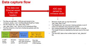
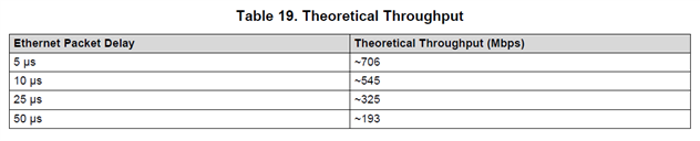
1. Based on the DCA1000 datasheet, the throughput can be changed with different ethernet packet delay.

However, it seems that the maximum value is ~706Mbps with 5us delay time.

Can you explain the meaning of packet delay time in this case, and plus, can we reduce the packet delay to increas the maximum throughput?

(i think the DCA1000 board uses 1000base-T ethernet phy chip, so the potential would be 1Gbps. is the reason of that comparably lower throughput caused by FPGA?) 

2. When we use sub-frame mode, can we send just some portion of the sub-frame?

For example, if we use 'a' and 'b' sub frame mode (ab, ab, ab, ab....etc.), can we only get 'b' part ADC data through the DCA1000?

(the reason why i ask this question is to reduce the total raw data size to fit the limited throughput)

  • Kim,

    Let me review your two questions and get back to you tomorrow.

    Regards,
    Kyle

  • Kim,

    This line is taken from page three of the DCA1000EVM User Guide:

     - LVDS data rates support a maximum of 600 Mbps. It supports both 4 lanes (xWR1243/1443) and 2 lanes (xWR1642).

    https://www.ti.com/lit/ug/spruij4a/spruij4a.pdf

    The throughput limitation is not a limitation of the FPGA or the Ethernet PHY used on the DCA1000EVM. This limitation is set by the maximum data rate of the LVDS High-Speed Interface. A gigabit PHY is needed because a slower 100 Mbps Ethernet PHY would not support the LVDS clock rates that are available on this device.

    The packet delay refers to the delay between the transfer of each UDP packet sent by the FPGA over the Ethernet PHY.

    And no, if you are using sub-frame mode, all of the ADC data will be sent out over LVDS and through the Ethernet PHY to the host PC.

    Regards,

    Kyle

  • Kyle,

    Thanks for your reply about my question.

    But i still could not understand the situation. If my explanation is not correct, could you tell me the right thing?

    I understand that the LVDS data rates support up to 900 Mbps for each lane. It means that if we use 4 LVDS lanes, the maximum data rate would be 3.6 Gbps.

    On the other hand, ethernet phy chip covers up to 1 Gbps based on the documents. So in this case, the maximum data rate between LVDS and ethernet phy could be ~1 Gbps. (the bottle neck in here is ethernet phy)

    But as mentioned in the page 26 of the document you provided above (spruij4a.pdf file), the theoretical throughtput can be set up to ~706 Mbps by setting the ethernet packet delay to 5 us.

    So coming back to the start, my question is,

    1. Can we set the throughtput up to ~1Gbps by using DCA1000 board? 

    2. If not, can we send just some portion of the sub-frame through the LVDS lanes?

    3. This is an additional question. What is the size of the UDP packet as you mentioned above?

        I think the size would be 'sequence number(2bytes)+data length(2bytes)+byte count(6bytes)+raw mode data(48~1462bytes)'.

        Is this calculation right?

    Best regard,

    Kim

  • Kim,

    I think you are confusing the the data rate with the clock rates of the individual lanes. The maximum supported data rate is 900 Mbps for LVDS, not 3.6 Gbps. And when using the DCA1000EVM, the User Guide states that the fastest supported data rate is 600 Mbps. This is not the data rate of a single LVDS line but the data throughput of the entire LVDS peripheral.

    The data rate combined with the number of enabled LVDS lanes determines the clock rate of each lane. I think you are assuming that all four LVDS lanes are enabled in all scenarios, and this assumption does not hold. This would not explain why the AWR1642 device with only 2 physical LVDS lanes can achieve the same data rate as the AWR1243 and AWR2243 that both have 4 physical LVDS lanes. So my conclusion from my previous post still applies.

    The bottleneck is not in the Gigabit Ethernet PHY or the FPGA.

    Please refer to the screenshot below for determining the size of the UDP packet.

    Regards,
    Kyle

  • Kyle,

    Thanks for your kind reply. But could you check this thread below?

    DCA1000EVM: maximum data transfer rate - Sensors forum - Sensors - TI E2E support forums

    As mentioned in here, i still think that each LVDS lanes can work at max. 900Mbps, hence the maximum data rate (potential) of the LVDS channel using 4 lane cases would be 3.6Gbps (AWR1243 & AWR2243)

    In addition, i'm currently using AWR2243 device, and i can use 4 LVDS lanes now.

    For example, if i want to transfer 100MB raw ADC data per 1 second, at least 800MBps data rate is needed.

    When i test this case with 5us packet delay time (700Mbps throughput), it seems that the raw data gathered just with some delay due to the data rate difference. And due to this difference 'DDR full' error occurs after few minutes.

    In real case, with 706Mbps throughput, received raw data would be around 15 GB before the DDR full error occurs, but in my case, this error happens with just ~10 GB raw data.

    I think the 706Mbps is just a theoretical value, so it may be a little bit lower in real case.

    So, going back to my first question,

    1. Can we reduce the packet delay lower then 5 us to increase the output throughput? (for example, 2~3 us)

    2. If not, when we use sub-frame mode, can we send just some of the sub-frame parts?

    Regards,

    Kim

  • Kim,

    You can certainly try to use a smaller delay packet than 5 us and see what the result is.

    As I mentioned previously, even when you use sub-frames, all of the ADC data will be sent out.

    Regards,

    Kyle

  • Kyle,

    In the mmwave studio setup, the value of packet delay can not be set under 5 us.

    Is there any way to set the packet delay lower then 5 us?

    Regards,

    Kim

  • Kim,

    If mmWave Studio limits the packet delay minimum to 5 us, then this is the lowest possible packet delay value.

    Regards,
    Kyle