This thread has been locked.

If you have a related question, please click the "Ask a related question" button in the top right corner. The newly created question will be automatically linked to this question.

IWR1843: The format structure of DCA1000EVM

Part Number: IWR1843
Other Parts Discussed in Thread: DCA1000EVM,

Hi Technical Support

I would like to know DCA1000EVM capture format as below.

C:\ti\mmwave_studio_02_01_01_00\docs\mmwave_studio_user_guide.pdf

I use IWR1843 with Tx Anntena × 3 and Rx Anntena × 4.

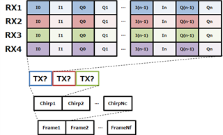
In that case, is it correct that the format structure of DCA1000EVM is divided

in the order of frame, chirp, Rx antenna, and Tx antenna as shown in the figure below?
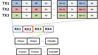


Best Regards.

  • Hello

    Have you looked the scripts/post processing examples in the  studio as these may be able to provide you further insight.

    The 16xx/18xx/64xx have same data format.

    Regards

    Vaibhav

  • Dear Vaibhav

    Thank you for your reply.

    Is it correct that You said "scripts/post processing examples" is "C:\ti\mmwave_studio_02_01_01_00\mmWaveStudio\MatlabExamples" ?

    I understood that my first recognize is wrong, but I still don't undetstand which is correct order of chirp and Tx as below.

    I will still check script, but if you could know, please tell me.


    And, I thaught the order of Tx is Tx1, Tx2, Tx3 at first.
    But I found figure as below.
    So, I'm not sure because it maybe the order is Tx1, Tx3, Tx2.

    Best Regards.

  • HI, there:

    Your first figure is correct.  Regarding the TX order, it is flexible, depends on your chirp design.  For example, if you first chirp enables TX1, second chirp enables TX2, and third chirp enables TX3, then the order will be TX1, TX2, TX3.  But if you change your chirp definition, this order will change accordingly. 

  • Dear zigang

    Thank you, told me.
    I understood that the order of Tx is changed by chirp definition.

    Best Regards.