This thread has been locked.

If you have a related question, please click the "Ask a related question" button in the top right corner. The newly created question will be automatically linked to this question.

IWR6843ISK-ODS: iwr6843 lost data bit when uart baudrate is 1843200 or higher

Part Number: IWR6843ISK-ODS
Other Parts Discussed in Thread: IWR6843

Hello

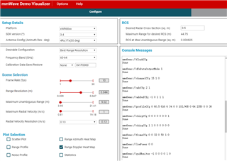
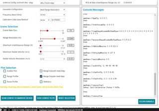
 We use iwr6843 ES2.0 and sdk version is 3.4.0.3.

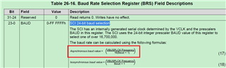
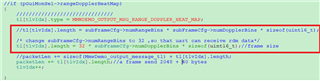
if config uartParams.baudRate   = 1843200  or   uartParams.baudRate   = 1920000 ,When receiving uart data, it was found that there was a bit loss problem.

I guess it may be related to the data sent by uart.

Please give some suggestions to help us verify the problem, thank you.

  • Hello,

    Can you please verify that there are no problems with a baud-rate of 921600. When you say that you are receiving data. Are you using the Demo Visualizer or are you using something custom on your end?

    Best,

    Connor Desmond

  • Hello,

    Yes, it's the same thing with a baudrate of 9216000. We use python app to receive uart data (RDM) in real-time.

    A frame of data is 1064 bytes, uart's bandwidth is enough .

  • Hello,

    The SCI 24-bit baud selection can only be an integer, does it support floating point operations? 

  • Hello,

    1. Since you are using python to parse your data I would suggest using the following parser to compare your implementation to, so that you can iron out the behavior which prompted this thread. It is located here:

    <MMWAVE_SDK_INSTALL_PATH>\packages\ti\demo\parser_scripts\mmw_demo_example_script.py

    This is fully functional script which should get you on your way.

    Best regards,

    Connor Desmond

  • Hello 

    We config commandBaudRate  = 1250000 bps, use cp2105's SCI to receive uart data(rdm),

    A frame size is  64*32*2, frame rate is 50hz, So the amount of data sent in one second is 81920 bytes;

    The baud rate is set to 1.25M bps, the bandwidth of uart is enough for transmission, but in fact, uart does not send data out. When the amount of data is reduced, the PC can receive the data of uart. We don’t know why. Please help to slove it, thank you.

    The following are the configuration parameters of the radar:

    sensorStop
    flushCfg
    dfeDataOutputMode 1
    channelCfg 15 1 0
    adcCfg 2 1
    adcbufCfg -1 0 1 1 1
    profileCfg 0 60.5 616 6 34 0 0 102.908 0 64 2350 0 0 30
    chirpCfg 0 0 0 0 0 0 0 1
    chirpCfg 1 1 0 0 0 0 0 0
    frameCfg 0 0 32 0 50 1 0
    lowPower 0 0
    guiMonitor -1 0 0 0 0 1 0
    cfarCfg -1 0 2 8 4 3 0 15 1
    cfarCfg -1 1 0 8 4 4 1 15 1
    multiObjBeamForming -1 1 0.5
    clutterRemoval -1 0
    calibDcRangeSig -1 0 -5 8 256
    extendedMaxVelocity -1 0
    bpmCfg -1 0 0 1
    lvdsStreamCfg -1 0 0 0
    compRangeBiasAndRxChanPhase 0.0 1 0 1 0 1 0 1 0 1 0 1 0 1 0 1 0 1 0 1 0 1 0 1 0
    measureRangeBiasAndRxChanPhase 0 1.5 0.2
    CQRxSatMonitor 0 3 5 121 0
    CQSigImgMonitor 0 127 4
    analogMonitor 0 0
    aoaFovCfg -1 -90 90 -90 90
    cfarFovCfg -1 0 0 8.92
    cfarFovCfg -1 1 -1.6 1.60
    sensorStart

  • Hello:

    My suspicion is that your frame rate is too high. I would suggest to lower the frame rate to start e.g. 30Hz. The issue may not be the UART at all. You see the more data that you collect per frame, the more time it takes to process that data. If the frame rate is too high then the next frame arrives before the data can be processed + pushed out over UART. This is why decreasing the amount of data fixed the problem. You have to find a balance between the amount of data collected per frame and the duration of that frame.

    Please try the following tool to generate a profile which meets your applications needs:

    https://dev.ti.com/gallery/view/1792614/mmWaveSensingEstimator/ver/1.3.0/ 

    Best regards,

    Connor Desmond

  • Hello: 

    Sorry , the frame rate is 20Hz,not 50Hz,i made a mistake. 

    frameCfg 0 0 32 0 50 1 0

    profileCfg 0 60.5 616 6 34 0 0 102.908 0 64 2350 0 0 30

    Radar transmit waveform time: (616+34+6)*32=20992us=21ms

    Frame period: 50ms

    Duty cycle is less than: 50%

    dss and mss are dual-core processing, bandwidth and idle time are sufficient, dss and mss are dual-core processing, bandwidth and idle time are sufficient, we only transmit range and Doppler heat map, I don’t know why uart can’t receive rdm data.

  • Hello:

    Let me check take your chirp profile to the relevant expert and I will get back to you.

    Best,

    Connor Desmond

  • Hello:

    Can you please try using the demo python script with the profile that you are using. I checked with the expert and they said your profile is okay, so lets try to iron out explicitly what the issue could be. Get back to me if you see the same behavior or something different.

    Best regards,

    Connor Desmond

  • Hello:

    I do not know how to run demo python script ( mmw_demo_example_script.py )to capture rdm data via uart.

    By the way,we can not receive any UART data with the serial port debugging tool.

  • Hello:

    Lets reset and establish a baseline. Can you please confirm some information for me.

    1. What are moving over point cloud over UART? rdm data? can you please clarify.

    2. Have you successfully ran through the Out of Box Demo. If not can you please go through that process.

    The script above takes the OOB Demo data, parses it, and places it in a .csv file. If you go through the source code for the parser script it should be clear how it works, so you can use it, but first lets verify through OOB demo that we can get data from the device and that there is not some HW dependency.

    Report back to me on these two notes and we will move forward.

    Best regards,

    Connor Desmond

  • Hello:

    1. rdm data is range-Doppler matrix,we set rangeDopplerHeatMap =1, so only transfer rdm data via uart port. If rangeDopplerHeatMap flag is      set, the log magnitude range-Doppler matrix,* size = number of range bins * number of Doppler bins * sizeof(uint16_t)

    2. Current sdk version is 03.05.00.04,It's working very well.

    3. I knew the python script to parse oob demo data, the oob demo data is transmitted through uart. Our current problem is that the chirp profile         configuration is ok, but the uart data is not received. 

    4. The baud rate is set to 1.25M bps, the bandwidth of uart is enough for transmission, but in fact, uart does not send data out

  • Hello:

    I have explained above why I need you to run the OOB demo. I understand what you problem is, but to support you I need to verify that UART is functional at the base-case e.g. OOB.

    Best regards,

    Connor Desmond

  • Hello: 

    The official demo (OOB) uart can work normally. We only modify the profile configuration file (as mentioned above), uart cannot receive data. We have calculated that the bandwidth of uart is sufficient, so we don’t know the root cause. please help, than

  • Hello:

    By "works normally" I would assume that that you are able to run the demo visualizer @ 921600 baud. With that established. I would make sure the following things work:

    1. Export the working config that you used for the OOB, and see if your parser can correctly parse the data. Do this @921600 baud. This will test if your parser is correct, or if there is indeed a problem with the configuration file.

    2. If that works then try doing the same thing at a higher baud rate. This will test if running at higher baud rates is the problem.

    Let me know what are the results of these.

    Best regards,

    Connor Desmond

  • Hello 

    1. If use as mentioned above config file ,No matter the baud rate is set to 921600 or higher, uart does not send data out .

        I am very confused about this, I don’t know the reason.

    2. The radar parameters are configured successfully, see the figure below:


  • Hello:

    We are going circles here. I need you to answer the following questions for my support to continue. Some of these may have been answered above, but I need a clear response.

    1. Are you able to successfully run the OOB demo @ 921600 baud (default baud)?

    2. Assuming (1) has been successful. Can you program your device with that .cfg file such that data is coming over the data COM port. If (1) is indeed working then you should be able to see that same data that is driving the visualizer over a PuTTY or Teraterm. Google these programs if you don't have them on your machine.

    3. Assuming (2) is functional. Implement your python script to parse the data coming through the COM port.

    4. If  (3) is functional. Then try changing configuration and see if it breaks.

    Best regards,

    Connor Desmond

  • Hello 

    We have verified that item1 ,item2, item3 is ok, there is no doubt about these.

    4. If  (3) is functional. Then try changing configuration and see if it breaks.

        ==> after we modify the profile cfg file, uart will not send any data.

               These cfg cli commands confirmed that they all responded correctly. 

  • Hello:

    Next I want you to note the deltas between the .cfg file that you have confirmed to have worked and the one that you are trying to implement now. Based on your response to those questions the UART is not the issue. It is the .cfg file.

    Change the working .cfg file one step at a time until it breaks. This will indicate which command or parameter to a command is causing the issue.

    Let me know what your results are.

    Best regards,

    Connor Desmond

  • Hello

    Those CLI commands are correctly parsed, and the mss host also responds with "done", and the indicator light of the radar turns green after the series of cli commands are written. It can be determined that these commands are no problem.

    The same cli commands Data can be received through Ethernet under iwr6843+dca1000.

     Can you please use these cli commands to run the demo code to see if uart can receive range and dropler data?

     Thank you very very much.

  • Hello:

    I don't disagree that your CLI commands come back with done, but since you are able to successfully get UART data using a different .cfg file then this verifies that UART is capable of sending data. Now you have stated that when you change .cfg file this results in data not being sent over UART. With that in mind I want you to tell me what change to the .cfg file specifically causes the system to go from sending UART data to not sending UART data, so that I can determine what effect that change has on UART or if something else is the cause.

    Please report back to me the change in the .cfg file that causes the UART data to come out.

    Best regards,

    Connor Desmond

  • Hello:

    The differences are as follows:

    The configuration file on the left can receive UART data, the configuration file on the right cannot.

  • Hello:

    Could you please identify which parameter in the profile configuration causes the UART to not send data out.

    Best regards,

    Connor Desmond

  • Hello

    The previous email has listed the differences:

    profileCfg 0 60.5 616 6 34 0 0 102.908 0 64 2350 0 0 30

    This cli command will cause uart to have no data output.

    This issue has been confused for a long time, Can you please use these cli commands to run the demo code to see if uart can receive range and dropler data? Thanks a lot !

  • Hello

    Any update for this issues?

  • Hello:

    I apologize for the substantial with my response. Let me test out the profile configuration that you highlighted above personally. I will get back to you soon and we can resume the debugging process.

    Best regards,

    Connor Desmond

  • Hello:

    I just ran the profileCfg that you gave me and it worked at a baudrate of 921600. This would indicate that the issue is not with the profile configuration or the UART on the device. Since it has been a little while can you please reaffirm that with the "erroneous" .cfg file that it still causes errors running the OOB demo @ 921600 baud.

    Best,

    Connor 

  • Hello

    If use this “profileCfg 0 60.5 616 6 34 0 0 102.908 0 64 2350 0 0",Can you receive uart data correctly? 

    What I mean is that there is no problem with the profileCfg . When using this configuration in the current application scenario, I don’t know why uart has no data output. This is the key point we need to solve.

  • Hello:

    The profileCfg command that you gave above: profileCfg 0 60.5 616 6 34 0 0 102.908 0 64 2350 0 0

    is not the same as: profileCfg 0 60.5 616 6 34 0 0 102.908 0 64 2350 0 0 30.

    The first command is missing the rxGain parameter of 30. If you do not include this command then the device will not be properly configured, and thus not display any output data.

    Assuming this was a copy and paste error. I have not been able to recreate your error. I have successfully ran the OOB demo at 921600 where there are no modifications to the profile configuration. You stated that this worked also for you. Is this correct? You then stated that the modification to the parameter list of the profileCfg led to the problem you had been seeing. I took the modified parameter list and applied it to my device and was able to drive the GUI visualizer no problem.

    Please verify that the profile configuration command that contains the rxGain paramter does or does not cause an issue for you.

    Best regards,

    Connor Desmond

  • Hello

    Sorry, this is a copy and paste error.

    I can successfully run OOB demo at 921600bps where there are no modifications to the profile configuartion.

    But if only modify profileCfg  0 60.5 616 6 34 0 0 102.908 0 64 2350 0 0 30 ,then no data output from uart data port.

    I checked with mmwave demo visualizer tool that the problem still exists(no data) use the following parameters :

    ----------------------------------------------------------------------------------------------------------

    sensorStop
    flushCfg
    dfeDataOutputMode 1
    channelCfg 15 1 0
    adcCfg 2 1
    adcbufCfg -1 0 1 1 1
    profileCfg 0 60.5 616 6 34 0 0 102.908 0 64 2350 0 0 30
    chirpCfg 0 0 0 0 0 0 0 1
    chirpCfg 1 1 0 0 0 0 0 0
    frameCfg 0 0 32 0 50 1 0
    lowPower 0 0
    guiMonitor -1 0 0 0 0 1 0
    cfarCfg -1 0 2 8 4 3 0 15 1
    cfarCfg -1 1 0 8 4 4 1 15 1
    multiObjBeamForming -1 1 0.5
    clutterRemoval -1 0
    calibDcRangeSig -1 0 -5 8 256
    extendedMaxVelocity -1 0
    bpmCfg -1 0 0 1
    lvdsStreamCfg -1 0 0 0
    compRangeBiasAndRxChanPhase 0.0 1 0 1 0 1 0 1 0 1 0 1 0 1 0 1 0 1 0 1 0 1 0 1 0
    measureRangeBiasAndRxChanPhase 0 1.5 0.2
    CQRxSatMonitor 0 3 5 121 0
    CQSigImgMonitor 0 127 4
    analogMonitor 0 0
    aoaFovCfg -1 -90 90 -90 90
    cfarFovCfg -1 0 0 8.92
    cfarFovCfg -1 1 -1.6 1.60
    sensorStart

    -------------------------------------------------------------------------------------------------------------------------

    Can you use these parameter to receive data from uart data port? 

  • Hello:

    I ran the configuration above. It is results in no data from from being sent to the GUI visualizer. The GUI visualizer also indicated that to display the azimuth heat map data to the visualizer you have to use a framerate less than 5, you are using 20. With that in mind I turned off the azimuth heat map and displayed the Doppler  - range plot to see if I could get data. I was able to. Try guiMonitor -1 1 0 0 0 0 0 instead to see if you get data. Overall though I believe that you device is functional you just need to step by step modify a known functional .cfg file and if it causes issues read the documentation as to why.

    Best regards,

    Connor Desmond

  • Hello :

    It has been confirmed that there is no problem with the profile config. The reason is that UART cannot receive data.
    In mss_mainl.c : MmwDemo_transmitProcessedOutput()
    Change subFrameCfg->numRangeBins to 32 so that uart can receive the data.

    Current uart baudrate is 1.25M bps, the bandwidth is sufficient,  So what the root cause is?

  • Hello:

    I would advise against changing the number of range bins directly to 32. In your .cfg file the number of ADC samples is set to 64. There is a 1 to 1 correspondents to the number of range bins and the number of ADC samples. Change this parameter to 32 and that should have the same effect. With that change in effect are you able to get the data out at the rate you desire?

    Best regards,

    Connor Desmond

  • Hello:

    I know what your meaning, But in order to get the UART data, I have to reduce the size of the output data.That's the question I asked at the beginning.

    At present, we use such a solution to do post-processing. Because we don’t know why the numRangeBins(64) * numDopplerBins (32) *2 +40 rdm data cannot be transmitted , a frame size is 64*32*2+40 (headers)= 4196 bytes.

  • Hello:

    The Azimuth Heatmap TLV as I mentioned earlier in the OOB requires a low frame rate e.g. 5. You are operating at 20. Since you are not able to get data out means that there was probably a timing violation. If you want to know the exact details of the violation then you will need to go into CCS debug run the OOB with the configuration that is failing and post a screenshot of the error so that I can give you answer. With this in mind there might not be a fix for what you want to do, so keep that in mind.

    Best regards,

    Connor Desmond

  • Hello

    We only need range and Doppler data (rangeDopplerHeatMap), other types of TLV do not need output, so 20 frames(rangeDopplerHeatMap) should be able to be output by UART

  • Hello:

    The next step is to run the project which does not send UART out in CCS as is described in the Out of Box User Guide. If UART is not being sent out that means something went wrong and our SDK should output an error that then we can move forward.

    Best regards,

    Connor Desmond