This thread has been locked.

If you have a related question, please click the "Ask a related question" button in the top right corner. The newly created question will be automatically linked to this question.

FDC2212: FDC2212DNTR Emission problem during RE

Part Number: FDC2212

Hi team,

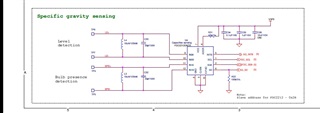
We are facing emission problem during conducting RE . 4,2 Mhz frequency is seen . This may be due to tank circuit of Capsense IC FDC2212 . Enclosing the schematic for the same. L3, L4 form tank circuit . V3P3 is IC supply 3.3 v Kindly review .
Enclosing the board file (layout ) for review ..U4 is the FDC2212 IC ,with L3 ,C32 ; L4 C33 tank circuit.
Can we try by reducing this operating frequency in terms of Khz ( instead of Mhz ) to reduce the noise. Will it work & have any effect on system performance ( capacitor measurement )?

 BMU-BLE-2V0-B-SAMPLE.brd

Best regards,

  • Hi Zhonghui,

    Thank you for posting to the Sensing forum.

    Is it possible to upload a picture of the board layout? I am unable to open the .brd file that you have attached.

    Additionally, where on the board are you measuring conducted emissions, and is 4.2 MHz the only frequency that is causing a failure?

    In the meantime, I also suggest reviewing the EMI Considerations for Inductive Sensing application note. Although it is targeted toward inductive sensing, it includes material on filtering that will relevant to your application.

    Best regards,
    Nicole

  • Hi Nicole,

    Thanks for your reply .
    1) I have enclosed the layout pictures for your reference.U4 is the FDC2212 IC ,with L3 ,C32 ; L4 C33 tank circuit.

     BMU ALL Layers.docx
    2). Also enclosing the register configuration setting done in our firmware for our measurements apart from mentioned in TI guide. What is impact on capacitor measurement due to change in these settings
    3)Earlier I had asked whether we can reduce the operating frequency to khz , Does it work or we need to operate @ 5 Mhz.

    Thanks,

    Best regards,

  • Hi Zhonghui,

    I have reviewed the register configuration and these settings should be fine for device operation. I noticed that the drive current for CH0 and CH1 is set to 1.571 mA, please make sure that this results in a sensor oscillation amplitude between 1.2 V and 1.8 V. Otherwise, registers 0x1E and 0x1F will need to be configured so that the sensor oscillation amplitude fits within this specification.

    In terms of operating frequency, the FDC2212 supports a sensor excitation frequency between 10 kHz and 10 MHz. For optimal performance, the deglitch filter will need to be adjusted if the frequency is decreased.

    Section 2.2 of the EMI Considerations for Inductive Sensing application note describes different passive filters to help combat EMI. Are any of these methods something that can be reasonably implemented in the system?

    Best regards,

    Nicole

  • Hi Nicole,

    Thanks for your reply.

    1)I had sent the layout pictures & schematic in earlier reply. Any feedback for the layout. During testing of our product for radiated Emission for EMC we observed the noise limit (dBm) above the range. Recommended components have been used 18uH & 33 pf

    2) Our observation is that during our values of register configuration noise is more . When the TI recommended values are set noise level has reduced. Any inputs for which registered may be causing this issues.

     8475.BMU ALL Layers.docx

    Best regards,

  • Hi Zhonghui,

    I recommend verifying that the drive current for CH0 and CH1 is correctly set. The sensor oscillation amplitude should be between 1.2 V and 1.8 V, as this may be the register setting that is causing difference. The recommended register setting listed in section 10.2.3.2 is 0x7C00, or 0.146 mA. 

    In addition, I would recommend using shorter traces to connect the sensor to the FDC. This can increase performance and help to reduce parasitic capacitances (section 12 of the datasheet).

    Best regards,

    Nicole