This thread has been locked.

If you have a related question, please click the "Ask a related question" button in the top right corner. The newly created question will be automatically linked to this question.

LDC1101: DRDY RP+L mode measurement with external timer

Part Number: LDC1101
Other Parts Discussed in Thread: TDC7200,

Hello there,

I would like to use LDC1101 in DRDY RP+L mode with external time measurement such as TDC7200 described in SNOA941A which should deliver that best achievable resolution possible. Latency between sensing a change in position (frequency of oscillation) and reporting it is crucial for my application.

As I read the LDC1101 reference manual (SNOSD01D) I found that Response_Time can be selected for multiple values based on required conversion time and resolution.

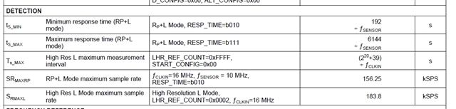
In 7.5 Electrical Characteristics of SNOSD01D It says that minimum response time (RP+L mode) is 192/Fsensor but maximum sample rate is (3xFsensor)/ResponseTime, where minimum Response Time is 192.

What does it mean that for response time it is 192/Fsensor and for sample rate (conversion time) it is 192/3x Fsensor? What is difference?

What is then actual latency between measured movement change and DRDY assertion)?

Thank you,

Michael

  • Michael,

    Thank you for creating the new thread.
    I will provide an update by COB tomorrow.

    Regards,
    John

  • Michael,

    I have been in the lab on an urgent customer issue and have been unable to get answers to all of your questions.

    I will have an update to your questions on Thursday.
    Apologies for the delay.
    Regards,
    John

  • Michael,

    I understand the confusion. After reading thru the data sheet, the relationship between these parameters is not obvious.
    The data sheet sometimes uses the variables Response Time and RESP_TIME interchangeably, and that is confusing.

    The DETECTION section in Table 7.5 gives the minimum and maximum Response Time as 192/f_sensor and 6144/f_sensor respectively.
    The values 192 and 6144 are simply the max and min values of the parameter RESP_TIME in the DIG_CONF register. I don't know why the table reports them this way. The table parameter Response Time doesn't seem to play a role in subsequent calculations.

    Equation 10 shows Conversion Time = Response Time/(3*f_sensor), and it should really be RESP_TIME/(3*f_sensor),which is the reciprocal of what the data sheet calls the Sample Rate
    The data sheet doesn't do a very good job of explaining how the Conversion Time relates to reporting, but the app note Performing L Measurements from LDC DRDY Timing states that a DRDY pulse appears via an INTB assertion on the SDO at the end of every Conversion Time interval (see Section 1 & Figure 1). Note that the app note uses RESPONSE_TIME  in place of RESP_TIME. 

    There is a spreadsheet tool available for download that has the LDC1101 equations (and others) built-in.
    You can download it from  here.

    Note that equation 6 in the data sheet shows: f_sensor = f_clkin x RESP_TIME/(2 x L_DATA)
    If you regroup and re-arrange the parameters you end up with  RESP_TIME/(3 x f_sensor) = L_DATA/f_clkin = Conversion Time

    I hope this helps.

    Regards,
    John

  • Thank you John.

    Best Regards,

    Michael