


Other Parts Discussed in Thread: MMWCAS-RF-EVM
We have a MMWCAS-DSP-EVM and a MMWCAS-RF-EVM. Currently we run the Cascade_MIMO*.lua example case scripts. So the relevant parameters are:
256 samples/chirp , 12 Tx antennas (a.k.a loop length), 4 devices, 4 rx Channel per device, 64 loops per frame and 10 frames.
We use Mathematica (which is "row first", "big-endian") and not Matlab (which is "column first" and "little-endian").
Findings so far:
The base number type is Int16 which consists of 2 bytes. The bit sequence of these bytes is:
Using the internal test source: {b7 b6 b5 b4 b3 b2 b1 b0} {sgn b14 b13 b12 b11 b10 b9 b8}.
Using the ADC: {b7 b6 b5 b4 b3 b2 b1 b0} {sgn sgn sgn sgn b11 b10 b9 b8}
Data entries in the bin files complex numbers.
Each complex number consists of two Int16 numbers, which involves 4 bytes. The first two are the real part and the last two the imaginary part of the datum.
Four such complex numbers in a sequence form a "RxQuad" and consist of the 4 receive channels of the sampled device {master,slave1....slave3}.
Given by samplesPerChirp, there are 256 such RxQuad in a sequence forming a "RxSweep". One "RxSweep" contains the measurement data on one single RFchirp for a given Tx configuration.
12 of such "RxSweeps" in sequence belonging to the Tx configurations 0 through 11, e.g looping through all possible Tx settings. A group of 12 "RxSweeps" are referred to as "Loop".
Using the test settings, 64of such "Loops" in sequence for a "Frame".
Using the test settings, 10of such "Frames" in sequence for the complete bin file.
1: QUESTION: Is this OK?
Especially is the sequence ok? The overall length would not be affected by this, so it is hard to find a mistake here. So, do you really save each Tx position forming a loop and then repeat loops? Would be logical but a tiny "yes" would improve our night sleep...
So the resulting equivalent of a single, complete bin file is a tensor with dimensions 10 x 64 x 12 x 256 x 4 , or "frames x loops x 12 x samples x 4". (Matlab folks: Read backwards and ignore top "frame" dimension )
Now the data is re-arranged as: 10 x 12 x 4 x 64 x 256 , or "Frames x 12 x 4 x loops x samples" (being more hierarchical)
Reading all four bin files transferred after capture, we glue the four 10 x 4 x 12 x 64 x 256 to one big 10 x 16 x 12 x 64 x 256 being "Frames x Receive x Transmit x ....
Now, we flatten the antenna dimensions 16 x 12 to one single dimension of length 192 by arranging the antennas in the sequence {Rx,Tx}: {1,1},{1,2},....{1,12},{2,1},{2,2}....{2,12},.....{16,12} resulting in an antenna index {1......192}.
Taking the geometry of the Transmit antennas, we have the following layout:
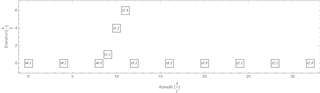
Taking the geometry of the Receive antennas, we have the following layout:
Combining all possible Rx and Tx configurations we have a geometry as follows (where only the leftmost part is shown and the plot is upside down):
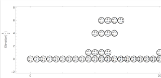
So therefore, the leftmost antenna phase center corresponds to Tx Device 4 channel1 together with Rx Device 4 channel 1.
2: QUESTION: Is this correct?
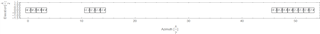
Repeating the same for all antennas but using the antenna index {1.....192} we obtain:
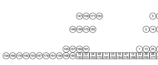
Now we note, that the squares show antennas positions that are redundant, e.g. 10 and 192.
This implies that e.g. (10): Tx-Chip 4 channel 1 Rx-Chip 1 channel 1 and (192): Tx-Chip 4 channel 3 Rx-Chip 4 channel 4 share the same phase center and should be related.
3: QUESTION: Is this correct? Are e.g. 10 and 192 duplicates? If not something would be wrong in the numbering scheme.
Plotting the absolute values of the scalar product of all antenna responses with each other, there is a certain tendency that this is the case (dark brown: less correlated 3500 , white: identical 0):
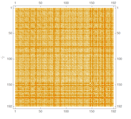
Clearly, there are some "weirdo" antennas around 150 and up which is to be expected since they are all single and the duplicates are heaped up around 100...120. Nevertheless, I would have hoped to have a clearer correlation response. (Just adding: the values on the diagonal have been replaced by 1500)
Thanks a lot in advance,
Yours
Harald
