


Other Parts Discussed in Thread: MMWCAS-RF-EVM
Hi,
I am using the MMWCAS-DSP-EVM + MMWCAS-RF-EVM kit. I experience a signal drop in the outer 10 % of the range.
I use the advance frame configuration to create the frames. The radar scans a sector from -60 to 60 degrees off-boresight in steps of 2 degrees.
Here are the main parameters I use to configure the radar from a Matlab file. Tell me if you like the JSon files.
%% define what angles to steer in TX beamforming mode
anglesToSteer = -60:2:60; % angles to steer in TX beamforming mode, in unit of degrees. 0 is boresight, positive clockwise
%% chirp/profile parameters
start_Freq_GHz = 77; % starting frequency for chirp, make sure the entire BW is within 76~77 or 77~81
slope_MHzperus = 20; % MHz/us
idle_Time_us = 25; % us
tx_Start_Time_us = 0; % us
adc_Start_Time_us = 5; % us
ramp_End_Time_us = 35; % us
sampling_Rate_ksps = 10000; % ksps
samples_per_Chirp = 256; % Number of samples per chirp
rx_Gain_dB = 30; % dB
% Frame config
nchirp_loops = 64; % Number of chirps per frame
num_Frames = 100; % number of frames to collect data
framePeriod = 500; % ms, instead of defining duty cycle (ON duration)/(ON+OFF duration)
%dutyCycle = 0.5; % (ON duration)/(ON+OFF duration);
% Only framePeriod or dutyCycle should be defined else the configration is over determined
%advanced frame config
chirp_Frame_BF = 0; % 0 - frame based beam steering, 1 - chirp based beam steering, 2 - as 1, but a trick to handle long chirps (more than 255) in one direction
numSubFrames = 1; %Currently only 1 subframe is defined
Main steps in signal processing
- FFT in range dimension
- FFT in doppler dimension
- Perform beamsteering towards the angle TX steering angles
The first figure is a heat map plot of a sea surface, showing cross range versus down range (both horisontal) of mean doppler.
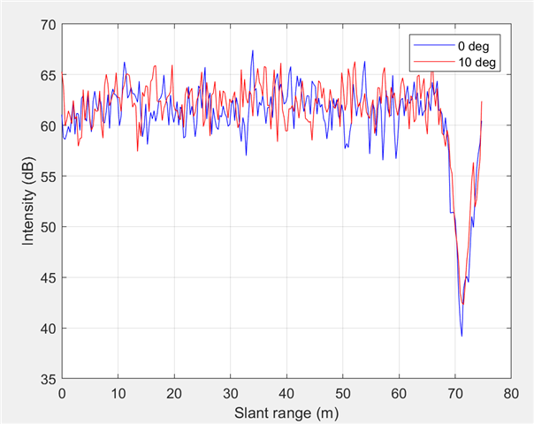
The second figure shows two single directions, 0 and 10 degrees off-boresight, from figure 1, but in slant range (antenna height = 5 metres).
I understand this is a tricky and complex question with probably to little information, but do you have any idea about what causes this problem?

Regards
Aanund
