Part Number: FDC2214
Other Parts Discussed in Thread: FDC1004,
Hi,
Can you please help me with the sensor design for FDC2214?
Hard requirements:
- Detect whether the moulded product is in or out of water.
- Remote sensing must penetrate 2mm of ASA plastic and 5mm of urethane.
- Variable excitation frequency (hence why we are testing FDC2214 instead of FDC1004)
Wishlist requirements:
- Detect whether the moulded product is in seawater or freshwater.
- Remote sensing must penetrate 2mm of ASA plastic and 8mm of urethane.
- Detect the rough salinity of the water the product is submerged in.
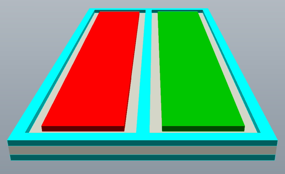
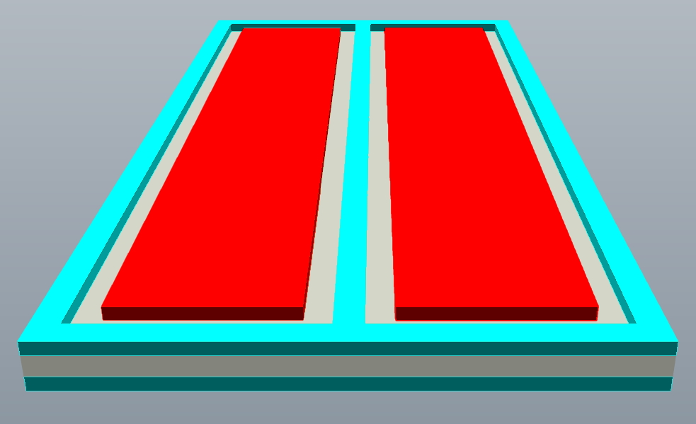
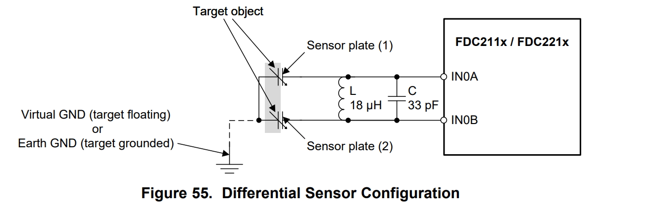
Single vs Differential Plate Configuration
Page 39 of the FDC2214 datasheet discusses the difference between single and differential plate sensor configurations. http://www.ti.com/lit/ds/symlink/fdc2212.pdf#page39
The single plate configuration allows for increased range while the differential plate configuration allows for better sensitivity at close range.
(1) How close is close range?
We need good sensitivity in order to detect the difference between seawater and freshwater but we also need to penetrate 2mm of plastic and 8mm of urethane.
(2) Would our application fall into the differential category (high sensitivity at close range) or the single ended category (long range)? We obviously need to test this, but since it’s expensive and time consuming to mould samples, we would like to have a good idea before we start.
Shielding
Shielding will reduce the effects of interference but will also reduce sensitivity. In order to get what we need out of the sensor I think we will need a balance. Hopefully we won’t need a shield at all so that we can get maximum sensitivity, but that is unlikely. I’m struggling to figure out how much is needed (e.g. undershield, guard ring, guard between plates, etc.) and how closely the shield signal has to follow the excitation signal.
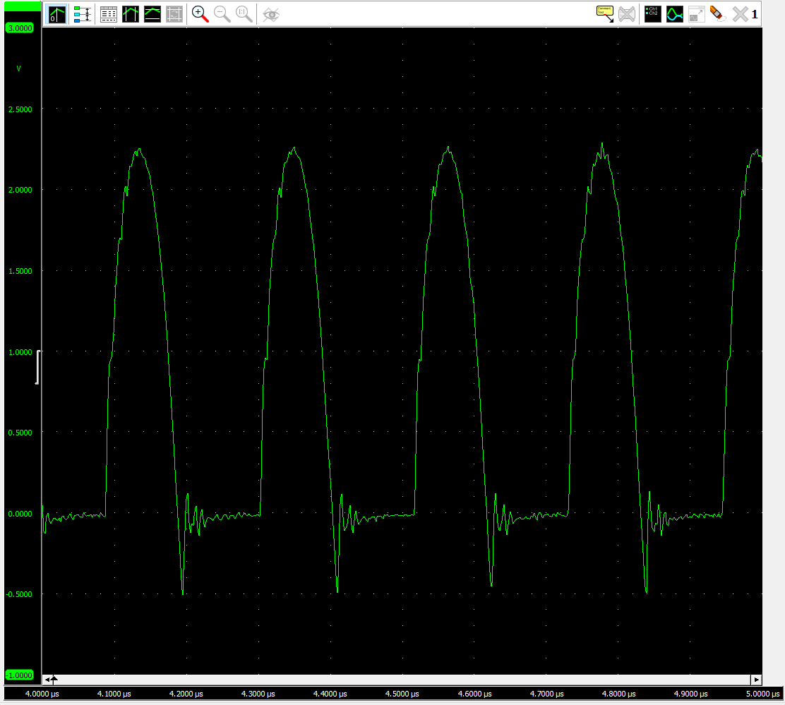
I’ve put together the following schematic for a shield driver using the EL8101 (slew = 160 V/µs min, 200 V/µs typical, bandwidth = 200MHz). R3 and RF are intended to help the op amp drive a capacitive load (the sensor).
EL8101 Datasheet: https://www.renesas.com/in/en/www/doc/datasheet/el8100-01.pdf

However, the problem is that it doesn’t trace the excitation signal very well with the largest deviation being roughly 633mV. From what I understand, if there is any potential difference between the shield and the signal, an unintentional capacitor is formed which reduces the sensitivity of the capacitor we intentionally create in the sensor.
(3) How accurately does the shield need to track the excitation signal in order to be effective? e.g. what deviation is acceptable?

(4) Is it possible to reconfigure how I’ve designed the shield driver schematic to make it more effective? Is there a better op amp? EL8101 was chosen because it would be effective across the entire excitation frequency range of the FDC2214. We don’t expect that we would need to use the maximum 10MHz but since we are unsure, we wanted a shield driver circuit that could handle it.
I've seen some threads mention that the op amp should have a split rail supply in order to allow it to output 0V. However, since quiescent current is a big factor in this design, we would prefer not to add a negative supply. (unless there is a very efficient way of doing it).
Kind regards,