Other Parts Discussed in Thread: FDC1004
Hi,
I am working on a project where I need to detect if a part is dry or submerged in water.
My plan is to use the FDC2214 with the sensor plates moulded behind roughly 8mm of urethane and 2mm of some currently undecided plastic.
We are waiting on the Dev Kit to start testing, but I suspect that we will need to add an active shield.
This E2E thread gave me a great start but I’m a little confused.
e2e.ti.com/.../2984719
There are a lot of E2E threads about the active shield but I haven’t found any that answer these questions in a way I understand.
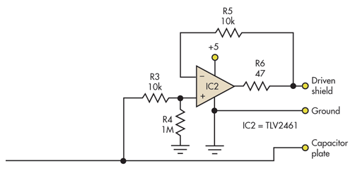
This article on driven shields is what’s confusing me. I think It’s using the approach where one of the sensor plates is grounded, which isn’t the case with the FDC2214.
https://www.electronicdesign.com/technologies/analog/article/21799482/driven-shield-enables-largearea-capacitive-sensor
1)
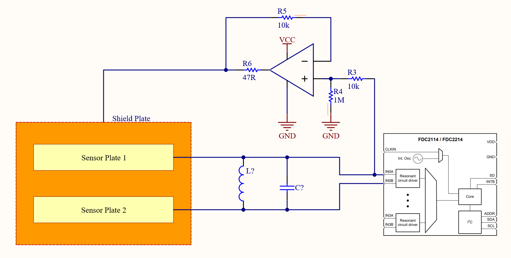
This is my interpretation of the circuit mentioned in the aforementioned E2E thread.
e.g. INxA and INxB each connect to a sensor plate. One of them also connects to the positive pin on an op amp with negative feedback and with the connection point being behind the LC tank circuit.
Is this circuit what I need in order to boost the capacitive input?
This is the approach I was going for:
(image from here: http://www.ti.com/lit/an/snoa935a/snoa935a.pdf )
2)
Am I correct to assume that I will still need the supporting resistors as discussed in the driven shield article?
R3 and R4 (and probably R5) prevent oscillation.
R6 helps the op amp drive the capacitive load.
Thank you for your help.
Kind regards,
Dan