This thread has been locked.

If you have a related question, please click the "Ask a related question" button in the top right corner. The newly created question will be automatically linked to this question.

IWR6843AOPEVM: Running Vital SIgn Demo on IWR6843AOPEVM but it doesn't capture data

Part Number: IWR6843AOPEVM
Other Parts Discussed in Thread: IWR6843, MMWAVEICBOOST, , IWR6843AOP

Hi,

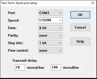
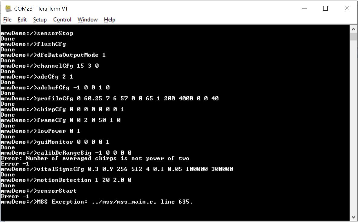
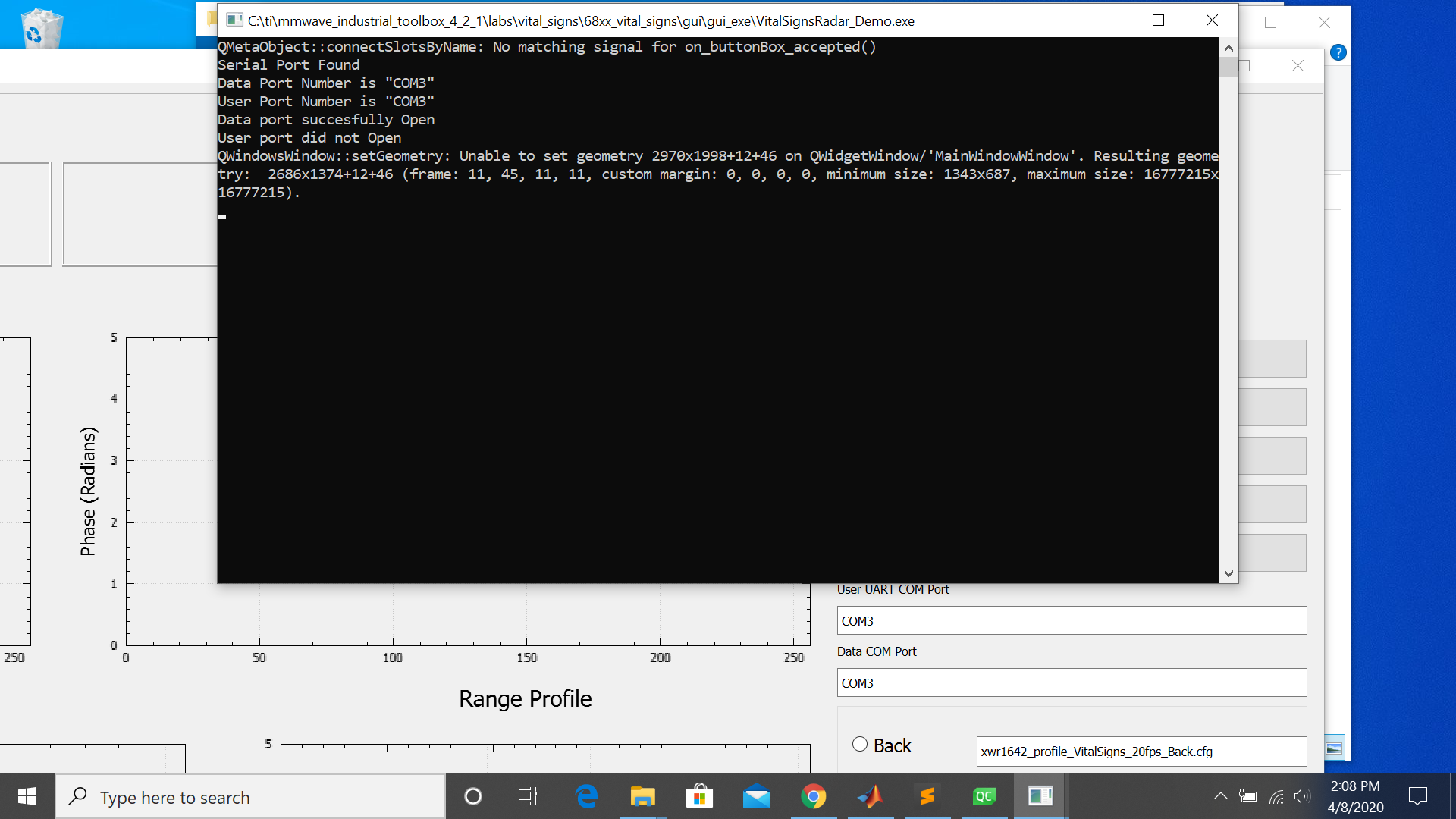
I'm using IWR6843 https://www.mistralsolutions.com/product-engineering-services/products/som-modules/60ghz-industrial-mmwave-radar-module/  and I'm trying to get it work with the Vital Sign Demo in the mmWave industrial toolbox 4.2.1, however, when I run the default demo GUI, it doesn't show any plot and the detected ports are wrong(it should be COM4 and COM5):

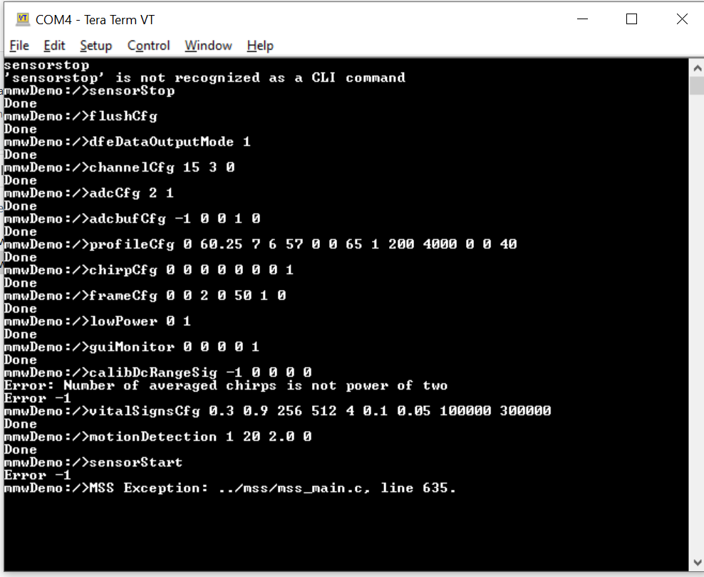
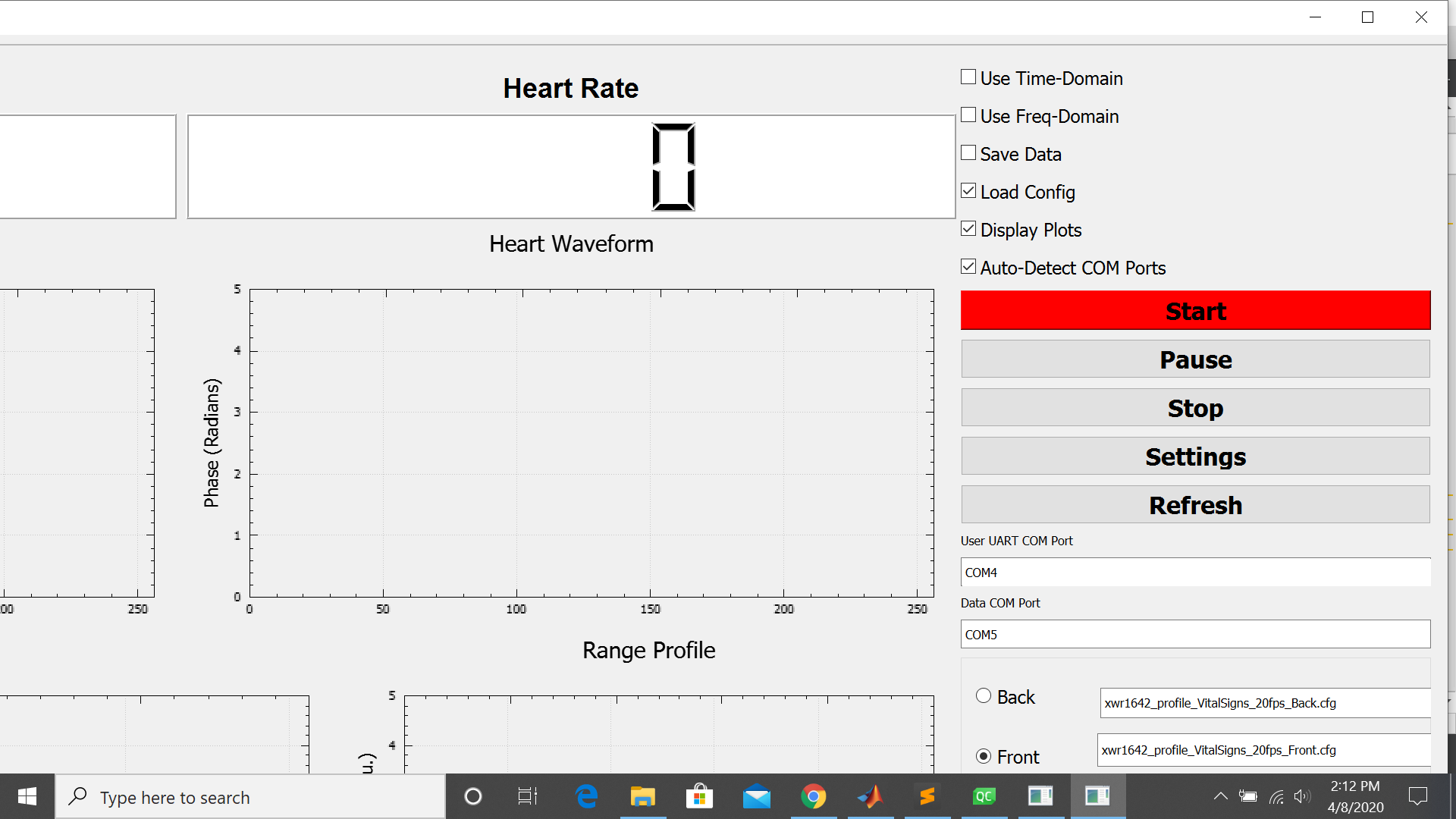
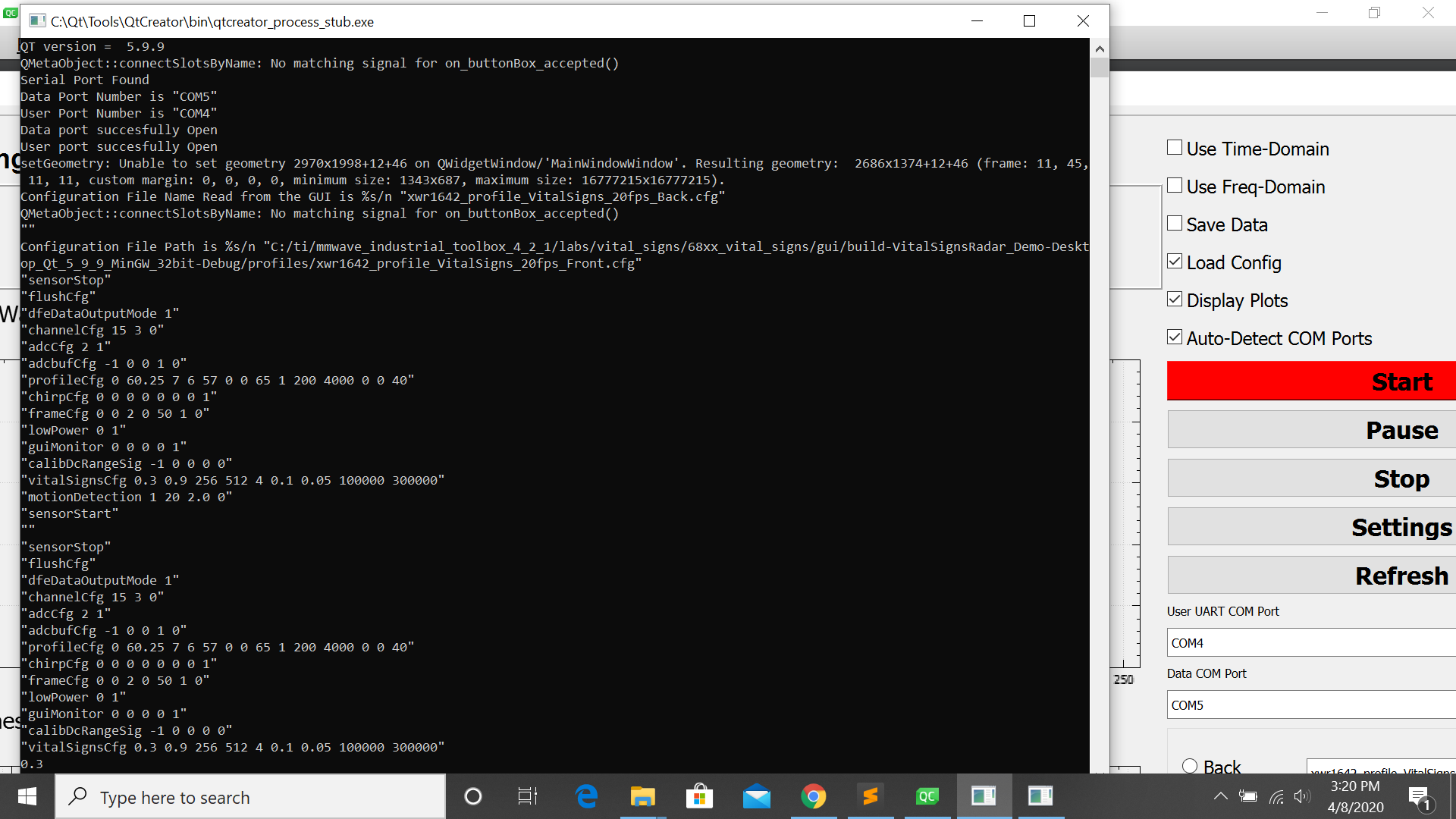
So I tried changing the GUI source code and setting the default port to be COM4 and COM5, however, it still doesn't show any plot, the results are shown as below:

I then also tried capturing data through the GUI and the recorded data file is empty, so I guess it's some setup errors...

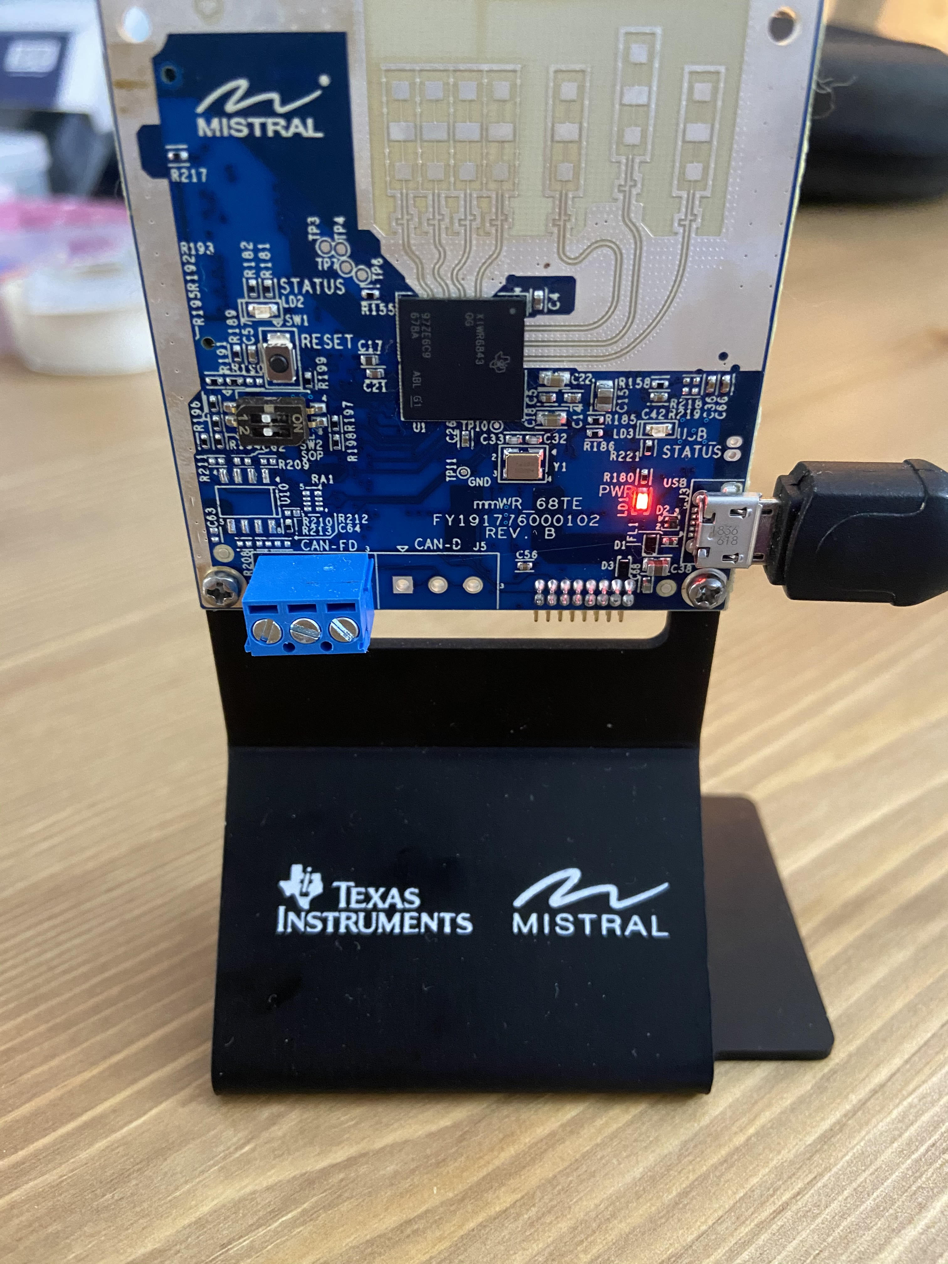
I have set the board correctly(both SOP1 and SOP2 are at "off") and it can run the out-of-box demo, I have tried flashing the board with vital_signs_demo_68xx.bin  and vital_signs_demo_68xx_aop.bin and none of them worked. Does anyone know why and how could I fix this? Thanks for your help!

Shirley

  • HI Shirley,

    Could you please try the following to help debug the problem?

    1. Is the Mistral module mounted on the MMWAVEICBOOST carrier card in the setup? Please share pictures of your complete board setup. 

    2. Have the Vital signs demo flashed.

    3. Apply power and press the NRST switch on the Carrier card to reset the EVM.

    4. Instead of using the GUI, connect Tera Term to the Control UART using the settings shown below (press enter a couple of times to make sure that you see the mmw demo prompt on the control UART port in Tera Term.

    5. Send the configuration commands in the provided .cfg file (C:\ti\mmwave_industrial_toolbox_4_2_1\labs\vital_signs\68xx_vital_signs\gui\profiles\xwr1642_profile_VitalSigns_20fps_Front.cfg) one by one

    6. Open another Tera Term Window and connect the Data UART using 921600 bps speed (keep all other settings the same as control UART).

    7. Do you see any data coming out (it won'be human readable) on the Data UART?

    Thanks

    -Nitin  

  • Hi Nitin,

    Thanks for the reply!

    1. I don't have a MMWAVEICBOOST carrier, is it required to run the vital sign demo? I can run the demo visualizer(https://dev.ti.com/gallery/view/mmwave/mmWave_Demo_Visualizer/ver/3.3.0/) without a MMWAVEICBOOST board. The setup I'm using is shown as below:

    2.I tried to use Tera Term to connect to the board,the control port is COM4 for me so I set it as COM4 instead of COM3 in your setup, and here is the commands:

    I opened another Tera Term window and checked Data UART(COM5) and nothing showed up.

    Do you have any ideas on how do I debug this or is it just because Vital sign demo requires a boost carrier? Thanks and I appreciate your help!

    Best,

    Shirley 

  • Hi Shirley,

    Thanks for providing this information. The TeraTerm log shows that the demo failed because of an exception in file mss_main.c at line 635. Did you make sure to Power cycle and Reset the EVM before starting the Vital Signs Demo?

    Regards

    -Nitin   

  • Hi Nitin,

    Thanks for the reply! Yes I did power cycle it every time and reset the EVM, I have tried flash the vital_signs_demo_68xx_aop.bin and vital_signs_demo_68xx.bin, and both gave me the same errors. Also there is another error when I send CalibDCRangeSig command, so that's probably a reason too. Do you have any idea why this is happening or how to fix this, thanks!

    Shirley

  • HI Shirley,

    We will need to run the demo in CCS debug mode to understand what's going on. The instructions to run the demo in CCS debug mode are available in the user guide section 4. Execute the lab under "Expand for help with Debug mode". You'll need to click on this item to open the debug instructions.

    Please run the demo in debug mode and look at the CCS console log (and provide snapshot) for any errors.

    Regards

    -Nitin  

  • Hi Nitin,

    Thanks for the reply! I'll dig into CCS debug and let you know the results. Thanks!

    Shirley

  • Hi Nitin,

    As per the above Tera Term log, the sensor is not started, throws Error -1.

    I'm also getting the same issue. Can you please share the configuration which is used for initial start of the sensor in vital sign demo?

    Thanks

    Arun

  • Hi Arun,

    The configuration is available in the following directory:

    C:\ti\mmwave_industrial_toolbox_4_2_1\labs\vital_signs\68xx_vital_signs\gui\profiles\xwr1642_profile_VitalSigns_20fps_Front.cfg

    Regards

    -Nitin

  • Hi Shirley,

    Did you try the demo in CCS mode on your EVM?

    Regards

    -Nitin

  • Hi Nitin,

    I tried the configuration mentioned above. Still not capture the data.

    In our EVM we are not using XDS110 debugger. Is the demo only work with XDS110 debugger?

    Regards,

    Arun 

  • Hi Nitin,

    I tried the ccs debug mode following the instruction here:

    And I got an error when click the "test connection" after I finish the target configuration setting, the error is saying "An attempt to connect to the XDS110 failed". I did some search online and found that most people having this error because of bad usb cable, however, the usb cable I'm using can successfully run the mmWave online demo visualizer so I don't think my usb cable has any problem, do you have any idea or suggestions?

    Below are the screenshot and error log, thanks! 

    [Start: Texas Instruments XDS110 USB Debug Probe_0]

    Execute the command:

    %ccs_base%/common/uscif/dbgjtag -f %boarddatafile% -rv -o -S integrity

    [Result]


    -----[Print the board config pathname(s)]------------------------------------

    C:\Users\SnowBall\AppData\Local\TEXASI~1\
    CCS\ccs1000\0\0\BrdDat\testBoard.dat

    -----[Print the reset-command software log-file]-----------------------------

    This utility has selected a 100- or 510-class product.
    This utility will load the adapter 'jioxds110.dll'.
    The library build date was 'Feb 13 2020'.
    The library build time was '18:30:11'.
    The library package version is '9.1.0.00001'.
    The library component version is '35.35.0.0'.
    The controller does not use a programmable FPGA.

    An error occurred while hard opening the controller.

    -----[An error has occurred and this utility has aborted]--------------------

    This error is generated by TI's USCIF driver or utilities.

    The value is '-260' (0xfffffefc).
    The title is 'SC_ERR_XDS110_OPEN'.

    The explanation is:
    An attempt to connect to the XDS110 failed.
    The cause may be one or more of: no XDS110 is connected, invalid
    firmware update, invalid XDS110 serial number, or faulty USB
    cable. The firmware and serial number may be updated using the
    xdsdfu utility found in the .../ccs_base/common/uscif/xds110
    directory of your installation. View the XDS110SupportReadMe.pdf
    file there for instructions.

    [End: Texas Instruments XDS110 USB Debug Probe_0]

  • Hi Nitin,

    In the above mentioned device is having CP2105 USB-to-UART bridge, Is that causing the issue?

    Regards,

    Arun 

  • Hi Shirley,

    The Antenna module does not have the XDS110 JTAG Debugger on it so you cannot connect CCS to it directly. You need to mount it on the MMWAVEICBOOST card (which provides the XDS110 JTAG functionality) and follow the procedure for CCS debug mode as listed in the user guide. 

    Regards

    -Nitin

  • Hi Nitin,

    Still we're debugging this issue.

    I found that there is no event received from BSS and failed to open mmwave module. But I didn't get the reason for why it is failing.

    The Out-of-Box demo is working fine. Only Vitals Sign is failing. I used profile configuration from "mmwave_industrial_toolbox_4_2_1\labs\vital_signs\68xx_vital_signs\gui\profiles\xwr1642_profile_VitalSigns_20fps_Front.cfg"

    This board is having CP2105 usb-to-uart bridge.

    As part of debugging I tested the USB data line, UART lines, Power and even tried by giving more power. Sill the output same.

    Can you please suggest some reasons why the communication between BSS is failing?

    Thanks

    Arun

  • HI Arun,

    1. Is this your custom designed EVM?

    2. Can you try to run the demo using Tera Term i.e. without using the Visualizer? Connect the control UART port at 115200 bps and the Data UART at 921600 bps and send the profile configuration on the control UART port Tera Term. Do you see any data coming out on the Data UART (it will not be human readable data since it's a binary data stream meant to be interpreted by the visualizer).

    3. Do you have a JTAG connection on your board like I replied above to Shirley?

    Thanks

    -Nitin

  • Hi Nitin,

    1. This is custom designed EVM.

    2. I run the demo using tera term by connecting CFG PORT to 115200 bps and DATA PORT to 921600 bps, and send the configuration via CFG PORT. No data coming in DATA PORT. After issuing sensorStart command it showing Error -1 and failing at line 635 in mss_main.c. 

    3. Yes it is having JTAG.

  • Hi Arun, Shirley,

    1. Could you please confirm which binary are you flashing? there are two binaries in the pre-built binaries directory:
      1. vital_signs_demo_68xx.bin: 
      2. vital_signs_demo_68xx_aop.bin
    2. Make sure you flash the first binary i.e. vital_signs_demo_68xx.bin as this is for ES2.0 silicon. The second binary (_aop.bin) is for AOP ES1 silicon and will not work. This is also mentioned in the user guide. Same applies for the CCS projects as well.
    3. Please flash the correct pre-built binary and share your observations.

    Thanks

    -Nitin 

  • To further clarify, your EVM is not the same as TI's AOP EVM. I think this confusion is coming from Mistral's naming. Their name AoPCB means Antenna on PCB which is not the same as the IWR6843AOPEVM (where AOP stands for Antenna on Package).

    The AOP binary provided in this lab is built for TI's IWR6843AOP ES1.0 Silicon, while the IWR6843 Silicon on your module is ES2.0 so you may be loading the wrong binary.

    Thanks

    -Nitin

  • Hi Nitin,

    Thanks for the support! I have tried using both vital_signs_demo_68xx.bin and vital_signs_demo_68xx_aop.bin, and both gave me the same results. I have contacted this evm board support team and they said they were facing the same issue when they tried running the vital sign demo. The support team said they are working on fixing it and will let me know once they have a solution. 

    Shirley

  • Thanks Shirley, Arun

    Please make sure that you use only the correct .bin file for IWR6843 ES2.0 i.e. vital_signs_demo_68xx.bin (and not vital_signs_demo_68xx_aop.bin) as I explained above. 

    I will close this thread for now. Please create a new thread, once you have more updates and if more support is needed on this topic.

    Regards

    -Nitin

  • Hi Shirley,

    Any updates on this? 

    Regards,

    Milad

  • Hello,

    Please refer to the following thread on the same issue:

    IWR6843: Sensor is not starting and capturing data when run Vital Sign Demo on IWR6843 based EVM

    As noted, the current Vital Signs Lab GUI only supports the UART COM ports exposed by the XDS110 UART controller (which is present on the MMWAVEICBOOST). The Mistral IWR6843 AoPCB EVM uses a different UART controller (CP210x) and the Vital Signs GUI does not work with those. So you will need to either modify the GUI to add support for the different UART COM ports or use an MMWAVEICBOOST as mentioned in the lab user guide.

    Regards

    -Nitin