This thread has been locked.

If you have a related question, please click the "Ask a related question" button in the top right corner. The newly created question will be automatically linked to this question.

AWR1642: Difference between profileCfg and real wave form

Part Number: AWR1642

Hello, TI team,

This is related with the URL below.
e2e.ti.com/.../971644

Now I set profileCfg as follows:
    profileCfg 0 76.1 7 7 18.24 771 0 10 -4 64 6250 0 0 48 

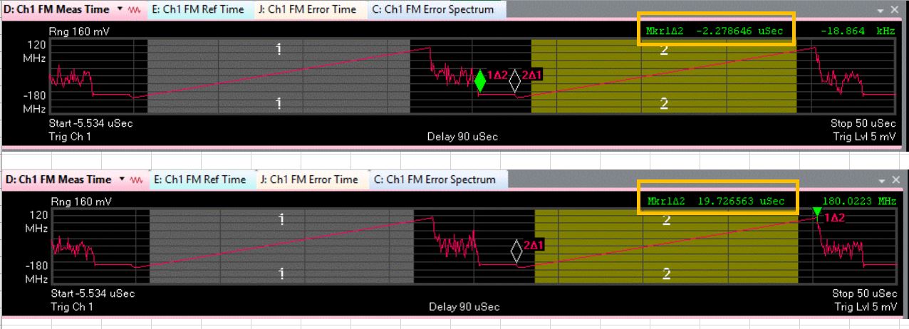
This means txStartTime is -4us, but the wave form below was observed.

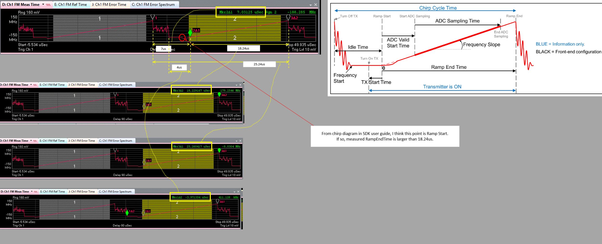
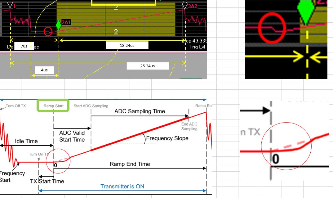
In the figure below, observed frequency constant time is about 2.3us, and ramp end time is about 19.7us.

I suppose frequency constant time will be 4us, and ramp end time will be 18.24us.

Why does the chirp look like the observed wave form?

Regards,

  • Please keep in mind the following pieces of information:

    - The total chirp time is the sum of the idle time and ramp end time

    - The TX start time has no impact on the total chirp time

    What you should do is measure the time from two peaks on adjacent chips and see what that time is. Then you measure 7 us from the peak to determine the ramp start time.

    In your ramp, the tx start time is -4 us, so the transmitter will turn on 4 us before the ramp start time.

    You should measure the width of the idle time (7 us) and see where those cursors line up in your plots.

    Regards,
    Kyle

  • Thank you for your reply.

    Please see the figure below.
    It is the measured chirp with profileCfg 0 76.1 7 7 18.24 771 0 10 1 64 6250 0 0 48.

    Chirp time is about 25.24us, so it is the same as the setting value, so it is OK, but there is one thing that makes me wonder.

    Regarding RampStart, is it at the red circle on the measured chirp? If so, RampEndTime becomes larger than 18.24us.

    Or is RampStart at marker 2delta1? If so, I think it is different from the figure in SDK user guide.

    Which is correct??


    Regards,

  • So the ramp start time happens at the end of the idle time. And the length of the ramp time is determined by the ramp end time. Our radar front end gives you the option of determining when to actually "turn on" the transmitter. The oscillator on the radar will continue to ramp. It just becomes a question of when the chirp is fed to the transmitter and sent out through the BGA ball and out through the antenna.

    Choose a positive value for the TX start time would mean the actual chirp would contain a subset of the theoretical chirp. This is also why the ADC start time value is typically larger than the the TX start time. This is designed so that the radar is sampling on the linear portion of the chirp. Some non-linearity may occur at the beginning and end of each chirp. That is why chirps are designed to sample a subset of the entire chirp and not the entire chirp, to avoid capturing the non-linear behavior at the beginning and end of each chirp.

    Regards,

    Kyle

  • I understood RampStart happens at the end of IdleTime.
    This means RampStart on my measured chirp is at the marker2delta1(2Δ1), correct?

  • Yes, based on your screenshot image, it would appear that the RampStart occurs where the 2Δ1 marker is placed.

    Regards,
    Kyle

  • Thank you for your answer. I understand, but according to the diagram in the SDK user guide, I think there is an undershoot at RampStart.
    But regarding to my observed chirp, RampStart is not at undershoot but at marker 2Δ1 as you said.
    Do you have any ideas why there is difference between observed chirp and the diagram in the SDK user guide?

    Regards,

  • The SDK diagram is just provided as a general reference diagram. You should not assume that the undershoot occurs at Ramp Start. This diagram is provided to help visually explain the different parameters of a chirp profile. Based on all of the information provided, I do not seen any discrepancy between the profile configuration and the observed output.

    At ramp start time, the output frequency should align with the start frequency of your chirp profile. Based on your screenshots, this is the observed behavior.

    At this point, I think this question has been explained in great detail. Please create a different thread if you have any other questions.

    Regards,

    Kyle

  • Thank you for your explanation.

    I understand.

  • Great! I am glad that you were able to get the explanation you were looking for. Please create a new thread if you have any other questions.

    Regards,
    Kyle