This thread has been locked.

If you have a related question, please click the "Ask a related question" button in the top right corner. The newly created question will be automatically linked to this question.

TPS62860: How to set the SW back to 0V

Part Number: TPS62860
Other Parts Discussed in Thread: USB2ANY

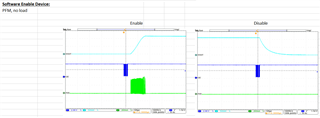
I am able to set VOUT to different voltages, However I want to set the Vout back to 0.

what register setting I should do. I tried just tried writing control register (0x03) with different values but SW not falling to 0.

  • Hello Pushpa,

    thanks for reaching out in E2E and for your interest in our products.

    The Vout discharge is done via the VOS pin by an internal MOSFET when the converter is disabled. The Output Discharge can be disabled with Bit 3 in the Control register, but it is enabled per default. This setting is then used for the next disable cycle (Software or Hardware).

    Let me know if you have further questions.

    Best regards,

    Andreas.

  • so what value i should write to control register in order to dischage output to 0V

  • Hello Pushpa,

    if the Control Register (0x03) is containing its default value (0x6B), then it should be sufficient to clear Bit 5 (Software Enable Device) by writing 0x4B. If the Control Register does not contain its default value, make sure that Bit 3 (Enable Output Discharge) is set. Then clear Bit 5 (Software Enable Device). The corresponding register value depends on the previous modifications.

    Let me know if you have further questions.

    Best regards,

    Andreas.

  • I can see the out SW toggling. but what is the difference between EN and software enable bit 5?

    if bit 5 of 0x03=1, SW =LOW

       bit 5 of 0x03=0, SW=HIGH

    what about EN it is also device ON and off right so, if I set EN=0, then SW=0, and EN=1, then SW=1 ???

  • Hello Pushpa,

    the EN pin and the Software Enable Device (bit 5 in Control Register 0x03) should be equivalent.

    What do you mean by SW=1?

    I would expect a rectangular waveform at the SW pin if the device is enabled.

    Have you also observed Vout?

    Here is a screenshot from our validation for reference.

    Best regards,

    Andreas.

  • What I observed is EN is default high. when this pin is set to 0 all the register settings will set back to default values. also I am facing lot of issue in writting python script for this. Am using a usb to i2c convertor which will drive the EN pin and I2C. but when i write code to i2c and gpio separately i can see the expected behavior but when I merge them together I am facing lot of issue. 

  • Hello Pushpa,

    you are right, in this aspect there is a difference in the functionality of the EN pin vs. Software Enable Device (bit 5 in Control Register 0x03). A high to low transition on EN is resetting the registers to the default values. Only the value of the "Enable Output Discharge" bit is latched until the next EN rising edge. Whereas the Software Enable Device (bit 5 in Control Register 0x03) is disabling the device with all registers values are still kept. But the Output Discharge (when enabled) is common to both methods of disable cycle (Software or Hardware).

    If your python script is for evaluation only then you could also use the solution of the TPS628600EVM-109. It provides the ability to program the registers via I2C with the help of a USB2ANY adapter and a User Interface (GUI) on the PC. Maybe this could also help as a reference for building your python script (comparing both setup I2C waveforms).

    Let me know if you have any further questions.

    Best regards,

    Andreas.