A related question is a question created from another question. When the related question is created, it will be automatically linked to the original question.
If you have a related question, please click the "Ask a related question" button in the top right corner. The newly created question will be automatically linked to this question.
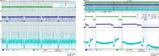
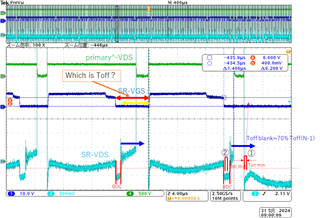
When pulse dropping occurs, the VDS transition seems to be fast. Is it possible that the threshold cannot be detected if the VDS slew rate is too fast?
That looks like it should have triggered the gate drive. Can you retake that waveforms with measurement of the Vds directly across the VD and VS pins of the UCC24612?
If VDD has 9.5 V and is regulated the signal across Vds should be great enough to initiate the gate drive of the FET.
You might want to check VDD to make sure that there are not noise spike on it causing the gate drive to disable.
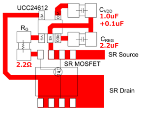
The other thing that you check is the voltage directly across VD and VS of the UCC24612 with a differential probe. Just to make sure it is seeing the same voltage that the Vds of the FET is seeing, when the missing gate drive pulse is observed.
The UCC24612 SR controller is provided in a 5-pin SOT-23 package which does not allow any programmability to adapt to different operating conditions. Instead, the device adapts to different SR situations by using a set of complex timing conditions to determine whether to turn on and off the SR MOSFET.
These timing conditions are discussed in the UCC24612 datasheet Section 7.3.3 with sub-sections 7.3.3.1 through 7.3.3.4 on pages 17-20 and the top of page 21. These discussions are complicated with a lot of details and may be difficult to understand. I admit that I find it difficult to fully understand.
However, I believe that the missing pulses that you are asking about are explained by this paragraph on page 20:
Because the SR current waveshape changes during the UCC28782 ACF operation (possibly because of its frequency dithering function), the timing changes cycle-by-cycle enough that sometimes (periodically) the previous off-blanking time is longer than the body-diode conduction time and the next cycle SR turn-on is skipped.
Because this is an automatic response by the SR controller to semi-repetitive timing conditions, I do not think there is anything that can be done with the controller to fix it. There may possibly be something that can be done with the UCC28782 control or with the ACF resonant structure to reduce how much timing variability happens, but that is a topic outside of this E2E thread.
I don't think it is simply a case of Toff time changing from long to short alone. There is at least one additional condition that must also be met, maybe more than one.
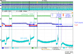
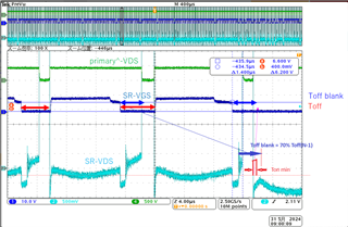
This example seems to fit the description highlighted in yellow in my previous reply. I suggest to examine several other cases of missing pulses to see if they all follow a pattern like this, where Toff time has become shorter AND the Toff blanking time extends beyond the last cycle's body-diode conduction time.
If most of the missing pulses follow a pattern, then we can conclude the cause of the missing pulses. Even if some do not follow the pattern, it may be that we cannot estimate the internal timing accurately enough. Unfortunately, we cannot see the timing that the controller actually works with internally, so we are left with estimating conditions based on external observations and try to fit them into the datasheet descriptions of expected behavior.
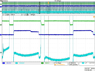
There are two body-diode conduction times to consider. I agree with your measurement of the body-diode conduction (BDC) time after the SR Fet is turned off. The other BDC time is the time before the SR Fet is turned on.
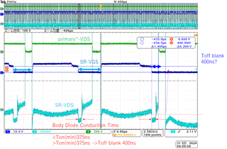
I believe that the off-blanking time is longer than 400ns, in this case, and starts farther to the right than where you indicate.
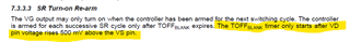
See this text in the datasheet, page 21:
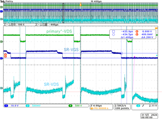
That makes the Toff blanking time look like this:
Since the last Toff blank time extends longer than the minimum Ton time, and the pre-turn-on BDC time is longer than Ton(min), the next gate drive pulse is skipped. So the SR FET in that cycle does not turn on in that switching cycle.
Thank you, I am beginning to understand it little by little. Could you please let me confirm a few points? -Toff blanking starts after BCD, but is the Toff time before or after BCD? -You said that conditions ① and ② are required, but which one do you mean by pre-turn-on, ① or ②?
1.last Toff blank time extends longer than the minimum Ton time,
2.the pre-turn-on BDC time is longer than Ton(min), the next gate drive pulse is skipped.
I am glad that it is getting clearer. Trying to explain it to you is also helping me to understand it better and helping me to explain it better. I wish I had more time available to draw some diagrams. That would really help a lot, but I am currently very time constrained and words will have to do.
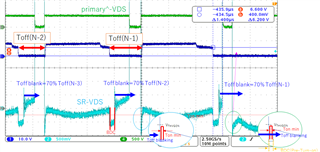
Toff time is the time interval between the moment the SR-Fet turns off (gate drive goes low) and the moment the SR-Fet turns on again (gate drive goes high). This is your red arrow time. Toff time may be different from one cycle to the next. Toff blanking time at the end of the current cycle is calculated from the previous cycle's Toff time.
Toff blanking starts when Vds > 0.5V. In the screen shot, the ringing at the end of BDC appears to exceed 0.5V which starts the Toff blanking timer. It is not the end of BDC that starts the timer, but when Vds > 0.5V. If there was no ringing, Toff blank would start when Vds rises because the primary MOSFET turns on.
If I understand you other question correctly, I believe that the pre-turn-on BCD corresponds to point ①. Normally, the pre-turn-on BCD time would be very short as seen in the first and second switching cycles in the screen shot. UCC24612-1 allows an 80ns turn-on delay after Vds exceeds the -240mV threshold. UCC24612-2 allows a 170ns turn-on delay after Vds exceeds the -240mV threshold. (The datasheet calls them propagation delays, but these are designed-in delays. The 16ns turn-off delay is a true propagation delay.)
At the start of the third switching cycle, the previous cycle's Toff blanking time extends into the third cycle. The pre-turn-on BCD would have triggered the gate drive turn-on, but the Toff blanking prevents it. However, the Ton-blanking time (minimum on-time timer) is still triggered even thought he gate does not turn on. Since the Toff-blanking time exceeds the Ton blanking time, the IC decides to skip driving the FET for this cycle, to avoid the chance of possible cross conduction with primary on-time. Since more than usual BDC time has occurred without SR turn-on, the SR controller cannot predict when the primary FET might turn on again and stays off for the rest of the cycle "to play it safe".
I have illustrated the cases where it turns on and where it doesn't turn on. Is this correct? If Toff Blanking passes during Ton_min, will it turn on at that point?
Yes, your drawing is correct. That is how I understand it.
Your question is a good one. I am not certain of it, but I believe that if the Toff Blanking time passes (expires) any time within the Ton_min time, the gate drive will turn on. How long it stys on after that will depend on other conditions.
This makes the most sense to me, since: If Toff_Blank expires somewhere in the middle of Ton_min and the SR-FET stays on for the rest of the cycle, it will be no different than a normal cycle except for a short turn-on delay (a delay less than To_min).
And if Toff_Blank expires somewhere in the middle of Ton_min and the SR-FET stays on only for the remaining Ton_min time and then turns off (for whatever reason), it will not be worse than having the SR FET turned on only for the full Ton_min time.