LP-MSPM0G3507: Checksum error while trying to talk to BSL on LP-MSPM0G3507

Part Number: LP-MSPM0G3507
Other Parts Discussed in Thread: MSPM0G3507,

Tool/software:

Hi,

I need some help on LP-MSPM0G3507 board. I want to interact with the ROM BSL in the MSPM0. I have flashed the bsl_software_invoke_app_demo_i2c_LP_MSPM0G3507_nortos_clang project and trying to run an simple host application which would try an i2c communication with it (via FTDI). 

I have formed the packet according to the bootloader userguide.

I have calculated the CRC with the following info from the userguide: 

"

CRC for the data must be calculated with:


CRC32-ISO3309 polynomial
Bit reversed configuration
Initial seed - 0xFFFFFFFF 

"

But when i run the application and and press s2 button to invoke BSL (invokeBSLAsm()) and then trying to run the host application, i always get a checksum error . 

For example the command is : 80 01 00 12 <calculated CRC>, the response will be 52 00 00 00 .....

I have also tried to flash the i2c plugin to this board and seeing the same behaviour. 

Can you help in getting to communicate to the BSL?

  • Hi,

    Do you use MSPM0 Bootloader (BSL) Implementation (Rev. C) as BSL user guide? I think you could refer 3.2 for using PC as BSL host, and the document also give the guidance of generating application image.

    Regards

    Pengfei

  • Thank you for the response. Yes, I am using the same document.

    I have a linux system and using python application to communicate with the MSPM0G3507. I am using the bootloader guide to generate packets with the required headers and cmd/data. The document mentions how to generate the CRC. We have made CRC also with the same instruction, but will get checksum error with that. 

    Is there any linux host example that can be used?

  • Hi. I am able to get past the CRC error. My application was packing the checksum in big endian mode. Put it LSB first and no longer seeing checksum error.

    Now when i run my application, i can see that the CCS window does not show error (it shows running). I can assume that it is in bootloader mode. 

    But none of the commands are returning any value. If I send "Get Device Info", it just returns 0x0000000000000000. I connected an analyser and confirmed that I am sending 80 01 00 19 B2 B8 96 49 (for get device info) [As mentioned in the MSPM0 bootloader user's guide]

    PS: I am using my own python application to communicate with the bsl.

  • Hi,

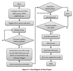
    Do you follow the steps below in your host script? Actually you could totally refer the example in SDK bsl_host_mcu_to_mspm0g1x0x_g3x0x_target_i2c_LP_MSPM0G3507_nortos_ticlang, which gives the complete flow of host to connect BSL device and send command.

    A tip from my side is to send 0xBB command to check target device status (see Status_check() function in the host example I mentioned above), and if the target is in BSL status, it will return a 0x51.

    Best Regards,

    Pengfei

  • Hi. 

    a) i wanted to confirm the hw connection/jumper settings for the board. I have removed the PA18 jumper, disabled that in the BSL configuration also.I have connected the J19 and J20 jumpers to 5v(pull up as mentioned in readme). I have connected my i2c sda and scl to PA0 and PA1 respectively. Is there any other HW connections to be done

    b) I am using the application to invoke the BSL by pressing the S2 button. From my application, i use the same flow as the example. But after sending BSL connection command, I see that the SDA and SCL lines are both low. Is there any extra pull up resistors that is required? 

    Also I can see the LED1 glow red after this. 

  • Hi,

    a) It is fine to pullup PA0 and PA1 to 5V. But just check whether the I2C interface of you host (PC) is open-drain. Besides, make sure the host and MSPM0 has common ground.

    b) As I2C is pull-up in a), no other pull up resistors needed. I think it is abnormal that you got always low after you send BSL connection command. Please make sure your connection from PC to I2C bus is normal. You could simply send some data by I2C from host, and see whether you could observe waveform in I2C but by logic analyzer.  

    Best Regards,

    Pengfei