Hello,
I am having issues with my TMUX1108.
Setup:
There are two TMUX1108's on my Arduino-type board, both sharing the A0, A1, and A2 pins, but with different EN pins.
Right now I am testing them with AA batteries (1.5v) ran to an ADC.
Problem:
The problem is, even when I have my AA input only going through one channel, I am getting the same reading on all channels.
So I am experiencing my 1.5v signal on all of the channels, even on the other TMUX1108 when its enable pin is low.
However, if I read just a single channel, I will get the correct value on that channel and 0.0v on the other channels.
So it has something to do with calling all the channels.
I am pretty sure that I am not calling the address pins correctly, so I am in search of some C/C++ sample code.
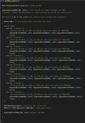
Here is a snippet of the code I am currently running with no success, but I've also included a screenshot thats easier to follow.
void setup(){

  Serial.begin(9600);

  pinMode(MUXA0, INPUT_PULLDOWN);
  pinMode(MUXA1, INPUT_PULLDOWN);
  pinMode(MUXA2, INPUT_PULLDOWN);
  pinMode(MUX1_EN, INPUT_PULLDOWN);
  digitalWrite(MUX1_EN, LOW);
}

void getMUX_Simple(){

  MCP.Configuration(1,16,0,1);// setup my ADC

  digitalWrite(MUX1_EN, HIGH); // Writing EN pin high to Enable the MUX
  //Should I enable the MUX before or after writing to the A0, A1, and A2 pins?

  for (int i = 0; i < 8; i++){//for loop to cycle through the 8 channels

    delay(200); // just being super safe with this delay

    switch (i){
      case 0: // channel 0
          //Writing A0 LOW, A1 LOW, A2 LOW per the truth table for TMUX1108
          digitalWrite(MUXA0, LOW); digitalWrite(MUXA1, LOW); digitalWrite(MUXA2, LOW);
          break;
      case 1: //channel 1
          //Writing A0 HIGH, A1 LOW, A2 LOW per the truth table for TMUX1108
          digitalWrite(MUXA0, HIGH); digitalWrite(MUXA1, LOW); digitalWrite(MUXA2, LOW);
          break;
      case 2: //channel 2
          //Writing A0 LOW, A1 HIGH, A2 LOW per the truth table for TMUX1108
          digitalWrite(MUXA0, LOW); digitalWrite(MUXA1, HIGH); digitalWrite(MUXA2, LOW);
          break;
      case 3: //channel 3
          //Writing A0 HIGH, A1 HIGH, A2 LOW per the truth table for TMUX1108
          digitalWrite(MUXA0, HIGH); digitalWrite(MUXA1, HIGH); digitalWrite(MUXA2, LOW);
          break;
      case 4: //channel 4
          //Writing A0 LOW, A1 LOW, A2 HIGH per the truth table for TMUX1108
          digitalWrite(MUXA0, LOW); digitalWrite(MUXA1, LOW); digitalWrite(MUXA2, HIGH);
          break;
      case 5: //channel 5
          //Writing A0 HIGH, A1 LOW, A2 HIGH per the truth table for TMUX1108
          digitalWrite(MUXA0, HIGH); digitalWrite(MUXA1, LOW); digitalWrite(MUXA2, HIGH);
          break;
      case 6: //channel 6
          //Writing A0 LOW, A1 HIGH, A2 HIGH per the truth table for TMUX1108
          digitalWrite(MUXA0, LOW); digitalWrite(MUXA1, HIGH); digitalWrite(MUXA2, HIGH);
          break;
      case 7: //channel 7
          //Writing A0 HIGH, A1 LOW, A2 LOW per the truth table for TMUX1108
          digitalWrite(MUXA0, HIGH); digitalWrite(MUXA1, HIGH); digitalWrite(MUXA2, HIGH);
          break;
    }

    MCP.NewConversion(); //initiate ADC conversion
    ORP[i] = (MCP.Measure()/1000.00); //take measurement

    digitalWrite(MUX1_EN, LOW);//disable the MUX

  }

}


