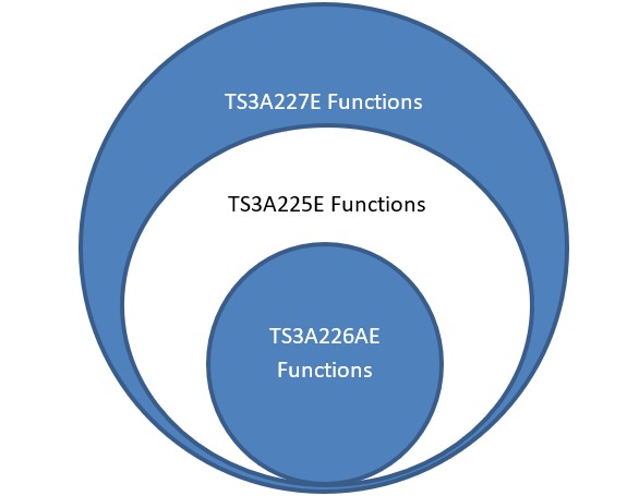
All of TI’s Autonomous Audio Accessory and Switch Routing IC’s (TS3A225E, TS3A226AE, and TS3A227E) all have the same common goal: to detect audio accessory type and to route ground and/or microphone signals between the audio codec and 3.5mm accessory plug. However, the functionality of the parts can be thought of as the functions of the 226AE is a subset of the functions of the 225E which is turn is a subset of the functions in the 227E – a visual representation is shown below.

This FAQ will briefly examine the similarities and then go into differences with each model.
All three devices have the following functions in common. First, all three devices can detect and route the following three audio accessory standards: 3-Pole, 4-Pole Standard, and 4-Pole OMTP standards. They use this with the same detection scheme which is explained in more detail here. They also all contain a pin that will trigger a detection – these transitions can be caused by insertion / removal of an audio accessory – for more information on how to do this please see here. Finally, all of them can support FM matching networks through different ground pins found on the devices.
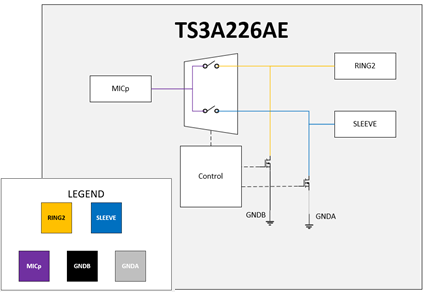
After the core principles of the device line – they begin to diverge from one another in function. First, looking at the TS3A226AE, this is the simplest of all three parts. This device is the only device within this family of parts that does not allow for software configuration. All the firmware in this device is pre-set and cannot be changed. One of the largest impacts of the lack of firmware control is the lack of control of the internal debounce delay; if more time than the 120ms programmed is required external RC capacitors will need to be added to the line. It also has the least number of pins since SENSE lines that are present within the other devices are not present on this device. However, the lack of SENSE lines and pins needed for I2C communication the TS3A226AE is the smallest out of all three devices with a footprint area of 1.44mm^2. This device is a good choice if space is constrained in the system and the default settings of the device work well for the application and a routing diagram is shown below.

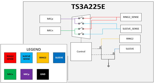
The next device on the list of complexity is the TS3A225E. This device acts similarly to the TS3A226AE – as the default settings for these devices are the same – but the 225E has additional features that make it easier to configure for the exact application. The first major change is the ability to configure the firmware of the device and change settings to meet your application. These changes can range from minor parameter changes such as changing debounce delays on the detection trigger pin to larger changes such as exerting full manual control over the device. These changes are all written through I2C communication – however this device does not support I2C Interrupts but it does have active low flag pin (/MIC_PRESENT) to trigger when a microphone is detected. The next major change is the addition of the SLEEVE_SENSE, RING2_SENSE, and MICn pins. The SLEEVE_SENSE and RING2_SENSE pins route the audio signals to the audio codec whereas the RING2 and SLEEVE pins are used in accessory detection and grounding either the RING2 or SLEEVE pin of the accessory. This differs from the 226AE which uses RING2 and SLEEVE for all these functions – however as a note it is recommended that SLEEVE is shorted to SLEEVE_SENSE and RING2 is shorted to RING2_SENSE. The other pin MICn is an extra route that allows the codec’s ground reference, if different from the rest of the system, to be routed through the switch to the accessory. In short, the TS3A225E is a good option for designers who want to be able to configure the IC through software to keep the IC flexible in its use allowing for easier system integration than with the TS3A226AE. A routing diagram for this device is shown below.

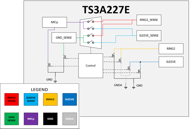
The final device is the TS3A227E. This device is a newer version of the TS3A225E – in which the 227E contains the same functionality as the 225E but contains more features. The first difference is the incorporation of an I2C Interrupt Pin which will activate upon completion of a state detection cycle to let the controlling host know when the state detection algorithm is finished. The next difference is that the debounce delay has a default of 90ms compared to 120ms of the previous two devices. Another minor difference is that MICn is now referred to as GND_SENSE. MICp and GND_SENSE also can be shorted to ground via FETS that connect these pins to the system ground via a lower impedance pathway than available with the 226AE and 225E. Another addition is the inclusion of depletion FETs used on the SLEEVE and RING2 connections of the device. These FETs are active when the device has VDD = 0V as depletion FETS can pass signals to ground with a 0V gate bias. This is helpful as it prevents humming noise through an audio accessory when the device is unpowered. The final difference in this part is the extra ability to add key press detection functionality to the IC. The 227E supports key press detection of up to four buttons allowing the button presses to be converted to I2C data that will be sent to the host/codec in the system giving the designer the flexibility to use the device to do some preprocessing of inputs on the accessory pathway. The TS3A227E is a good choice when a designer wants software configurability, interrupt support, audible noise reduction at power off conditions, and/or the ability to pre-process button presses on audio accessories. A routing diagram of the device is shown below.

All these devices allow the designer a device that will automatically detect and route audio accessories appropriately based on accessory type. The differences discussed above are summarized in the below table.
|
DEVICE |
3-Pole |
4-Pole Standard |
4-Pole |
FM Support |
CODEC Ground Return |
RING2 SENSE |
SLEEVE SENSE |
I2C |
INT support |
/MIC PRESENT |
Depletion FETS |
Keypress Support |
|
TS3A225E |
Yes |
Yes |
Yes |
Yes |
Yes |
Yes |
Yes |
Yes |
No |
Yes |
No |
No |
|
TS3A226AE |
Yes |
Yes |
Yes |
Yes |
No |
No |
No |
No |
No |
No |
No |
No |
|
TS3A227E |
Yes |
Yes |
Yes |
Yes |
Yes |
Yes |
Yes |
Yes |
Yes |
Yes |
Yes |
Yes |

