This thread has been locked.

If you have a related question, please click the "Ask a related question" button in the top right corner. The newly created question will be automatically linked to this question.

TMUX1209: Muxes keep breaking without warning

Part Number: TMUX1209
Other Parts Discussed in Thread: TMP107

We have a 2 * 1:16 multiplexer device, which communicates with sensors and reads battery voltages. When measuring the batteries, we have an in-line resistor to protect from over current draw which has fired multiple muxes in the past. On a brand new set of these muxes, that were only used to communicate with sensors (DS18B20, and TMP107) we see that sometimes these muxes stop working at random, and need to be replaced often. We had muxes just open all the switches at once, even when the EN line was pulled low, and sometimes a single channel breaks and the mux becomes useless. Is there something that we can do to eliminate the failure rate of this mux?

Its powered at 3.3V, with the sensor logic also at 3.3V, the communication line is pulled up to 3.3V with a 10K resistor on all channels. When measuring the batteries the muxes switch to a 5V supply, with the batteries never exceeding 4.2V.

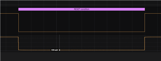
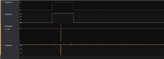
The attached pictures show the EN line on channel 1, and the Data transmitted by the master to slave 3 on channel 3. Digital waveform on top, and analog on the bottom. I sent a photo of a broken mux, and a working mux which was just replaced. The broken mux has one message on channel 3 as apposed to 16 messages on channel 3 on the broken mux.

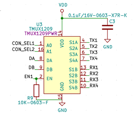
the mux has a 0.1uF capacitor on its input power, and the EN line is pulled low with a 10k resistor.

  • Hi Omar,

    Thanks for providing these details regarding your application. I have a few questions that would help clarify the exact situation you are experiencing:

    1) Is the power to the mux active at all times? Is there an instance where the VDD is powered down on the mux and there is a signal present on the input pins still?

    2) What is the value of the current limiting resistor you are using? These devices can only sustain 30mA of continuous current. Need to be sure that you are limiting the current enough to never exceed this absolute maximum value.

    3) Do you have a full or partial schematic you can provide to get some more insight on every aspect of the circuit setup?

    Thanks!

    Bryan

  • 1) the power to the mux is set at the start and never changed when the power is on, so it is either always connected to 5V or 3.3V

    2) We don't have an exact value of the current that goes through the mux when communicating with sensors, but it is definitely lower than 30mA. The master has a set drive current of 1mA. The slaves will likely have a maximum drive current of 10mA MAX. There is no inline resistor when sensors are plugged in. But, when there are batteries plugged in we have a 1k in line to reduce current to below 5mA.

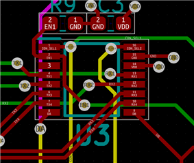
    3) I have attached a schematic and a layout snippet. 

  • Hi Omar,

    Thanks for helping clarify. On the first point, you mention that the power to the mux is set at the start. Are you positive there is 0V present on all inputs prior to power up? There is no battery voltage or sensor voltage present before the mux powers up? Need to be sure the inputs and outputs see less than or equal to the power supply otherwise you can damage the device.

    Schematic and layout look fine to me. The failure indicates there is some overstress/transient event happening at some point during your communication with the device. Do you have scope shots of the VDD pin and both the inputs and outputs during the transmission?

    Thanks,

    Bryan

  • Hi Bryan,

    Sorry I accidentally marked this as resolved. 

    The device has 16 ports that the user can plug things into. The user will not have anything plugged in when the device is powered up

    When the device is powered up there are pullups on both the input and output sides of the mux. The pull-ups are needed for communication

    Here are scope images of a random output (pin 7), A random input (pin 9), and VDD, upon start up.
    top 2 channels are Input and output pins off the mux. and channel 3 is the VDD pin on the mux

    We captured a power up and power down of the device. Since there was something weird on the power up we captured it twice and attached it here. the entire power up is around 10 ms


    For the transmission, I have the input and outputs on channel 1 and 2. and the VDD on the mux on channel 3

  • Hi Omar,

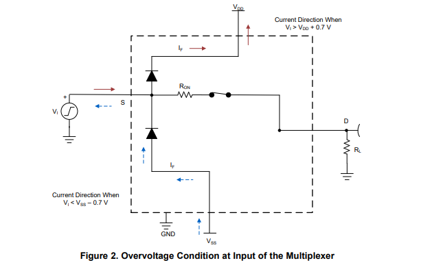
    That is quite odd behavior during the ramp of the power supply. The problem during this ramp is that the input/outputs exceed the VDD voltage by more than 0.5V which can cause damage to the device during that time period. The reason this happens is due to the ESD diodes in the device turning on and causing current to flow through the diodes which can damage the part if not limited (see below):

    This is why you need to ensure the VDD is completely powered before ramping anything else, otherwise you can induce damage inducing conditions. While this may not guarantee damage every time, this repeated overstress can damage the device over time which could also explain why you see devices fail "randomly".

    Hope this helps clear things up.

    Thanks!

    Bryan

  • Hi Bryan,

    Thank you for the help, I really appreciate it.

    This explains everything, as we have never had a mux fail during operation, but rather just on reboots.

    We have to do a bit of testing to ensure this does not happen again, if something else comes up I will open another ticket if this does not resolve it, I hope it does though, from the scope I can read the voltage difference to be just over 1.5V at the most, which would cause more frequent than usual failures. 

    Again, thank you for the help!

  • Hi Omar,

    You are welcome! Let me know if there are any other issues!

    Thanks!

    Bryan

  • Hi Bryan, 

    I was still thinking about the graphs from yesterday and how it was difficult to believe that VDD would have noise while the pullups did not, and I am sorry to inform you that I found an error on my end. My graphs were swapped. Channel 1 was VDD, channel 2 was the Slave, and channel 3 was the master, which is plugged in at start, hence the noise on the graph. 

    I am not sure if we can continue on this ticket or if it is better to open another?

    Omar

  • Hi Omar,

    We can continue our discussion here.

    So since you said this failure is happening on reboot (can you confirm this is always the case?), this means there could be a transient event happening on the power up or power down phase of the cycle.

    Also, what exactly is the failure mechanism that is occurring? I think in the original photos you shared it was that the communication only transmitted one signal as opposed to 16 (is that correct)? With that, I would think something strange is happening with the SPI master then...can you confirm that even with a "broken" mux that the SPI master is still properly communicating the right signals. It is odd that the line transmits nothing after one signal.

    Thanks,

    Bryan

  • Hi Bryan,

    I cannot confirm 100% that it is just on start up, but we never had a mux blow during normal data logging, we had the device running for days and we never had it burn out in the middle of a test. We find that a mux no longer works when we want to run a new test, where the device has been unplugged from the wall, and all sensors have been unplugged, THEN power gets re-plugged, and sensors get re-plugged. 

    For reference the device is getting powered by a buck regulator which powers a raspberry pi at 5V, then the raspberry pi steps the voltage down to 3.3V, then every 3.3V device uses that voltage if that voltage is selected. The voltage is selected by a physical jumper that is only moved between 3.3V and 5V during power down.

    our device has 16 ports each with their own RX and TX, we have a mux for every bank of 4 devices getting switched so DA and DB on the mux would represent RX1,RX2,RX3,RX4 and TX1,TX2,TX3,TX4 respectively for a set of 4 devices, and we have this 4 times in our device, for a total of 16 pairs of RX/TX ports, which means 4 muxes total. Depending on the device selected and which bank it is in, only 1 of the 4 muxes gets enabled at any given time to select. all 4 muxes share the same addressing pins but each with a unique EN pin. 


    So from my previous snapshots a non working mux would have the input (DA) connected to all outputs at once (RX1,RX2,RX3,RX4), and even when that particular mux gets disabled DA still connects to all lines. This causes the master to detect devices on all ports even when there is only a single sensor on a port. 

    The signal is slightly different from the master if the mux is broken, the mux will transmit the same, slightly weaker signal to all channels regardless of selection or EN pin status. When the master pulls the line low it would only go down to 0.9V as apposed to 0.2V with a working mux. This is still read as a 0 by the slave and therefor it responds which is read by the master as a response.

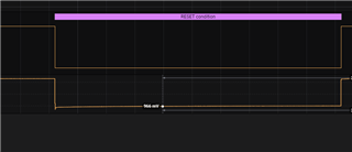
    The pulses seen below are 1ms long.

    We also had muxes stop working completely on just a single channel, and no matter what it won't transmit data through that line. We also had muxes overheat to the point where residue flux was boiling off the IC, but we know that this is due to over current, unlike the other malfunctions. We had gone through over a dozen muxes at this point. 

    Thanks 

    Omar

  • Hi Omar,

    Can you explain more about what happens when moving from 3.3V to 5V? How does this happen (or does it only move from 5V to 3.3V)? Is VDD set prior to connecting to the sensors at the 3.3V/5V?

    It may be a good idea to scope the problematic channels during power up/power down as well...I know you confirmed this for one input/output, but do they all behave similarly? Is there one sensor or input to a particular mux that is getting damaged?

    Thanks,

    Bryan

  • The device will never change VDD when connected to power. The only time VDD changes is when the power is completely off and disconnected, then its changed by moving the position of a physical jumper on the PCB. VDD is set prior to power up and the connection of sensors.

    At the moment we do not have any damaged muxes that I can collect data from, we replace them as they break. We have only had one case where a single channel broke. the more common case is the mux connecting all the channels together at once. I am sorry I cannot capture a broken mux at the moment. We did not notice the muxes breaking with a certain type of sensor, and more commonly there is no single channel that is damaged but rather the whole mux

    Thanks 

    Omar

  • Hi Omar,

    If all of this you are saying is true, then there is more going on in your system that you have to investigate as there is some fault event or transient event occurring that I cannot see or guess as I only have this limited scope. I would advise taking a close look at all of your inputs and outputs on the device on powerup and powerdown to ensure they look normal. These parts do not just break without some event like this happening. Lastly, you need to make sure that those current limit resistors are working as intended as the claim is that this has been resolved, but parts are still being damaged.

    If you have any other information you would like to share, feel free to do so. I will do my best to look at it, but based on everything we have looked at, this leads me to believe there is some overstress event happening that you need to be able to track down somewhere in your system.

    Thanks,

    Bryan

  • Hello Bryan,

    I just thought of something that may be the cause of the issues we are having. 

    The master controls the muxes on board with 4 muxes sharing the same 3 address lines(S0,S1,S2), the master drives all these lines at a drive current of 1mA, the EN is controlled by something else. Would a low drive current hinder the functionality of the muxes?

    I did not find anything that outlines this in the spec sheet.

    Thanks,

    Omar

  • Hi Omar,

    I would say it is unlikely that 1mA would not be enough across all the data lines. However, this depends on what else the master is driving. As long as the VIH/VIL voltages are being met, the multiplexer should act appropriately. Based on the scope shots you have presented, it seems they are getting the voltage they need to operate so there should not be any issues with the addressing. Not a bad idea to put a scope on all the pins to make sure they are behaving as expected though.

    Thanks,

    Bryan

  • Hi Omar,

    Have not heard anything in the last few weeks regarding this issue. Going to close this thread for now, but feel free to reopen if you have any other questions.

    Thanks!

    Bryan