


How do I select the right analog switch and mux bandwidth based on the data rate of my protocol?
Bandwidth has a specific definition when referring to TI IC’s. When discussing a device’s specific bandwidth, it refers to the maximum analog signal frequency of a sine wave that can be passed through the device with a specified loading condition given in the data sheet before the signal is attenuated by 3dB, or loses half the signal power. Given that bandwidth is most often measured in Hz, or cycles per second, bandwidth simply refers to the maximum frequency of the analog signal passed through the device. However, this is often used interchangeably with data rate. Given a signal protocol, data rate and specifications of the protocol need to be used to determine the minimum bandwidth required when selecting a TI mux.
In order to determine the bandwidth of the mux needed to support a given data rate, it is important to note the protocol. The number of signal levels per cycle encoded in the signal details the amount of data in one clock period that is transmitted, and is relevant to determining the bandwidth. In the figure below, the red signal reads two bits per cycle, one on the rising edge and another on the falling edge of the clock. The blue signal reads only one bit per cycle on the rising edge.
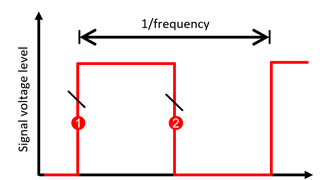
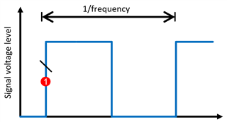
While the clock frequency is the same for both of these signals the data rate specified for the red signal would be twice the blue signal’s data rate. Despite two different data rates, a mux with a bandwidth large enough to sufficiently pass the blue signal would also perform similarly with the red signal. Therefore, the conversion between data rate and bandwidth must compensate for this.
The square wave bandwidth needed can be determined using the equation below:
Bandwidth (square) = Data Rate / (# of lines x bits per cycle)
However, when solving for the square wave bandwidth of the IC, it is important to note that frequency composition of a square wave has a fundamental frequency and many harmonics while a sine wave frequency composition is a single fundamental frequency. To account for this, it is good practice to select a device with the listed bandwidth as 1.5 times the square bandwidth calculated above. For highly sensitive signal chains, it is best practice to select a device with 3 times the bandwidth.
As an example, there are many different ethernet protocols, the latest and fastest being Gigabit ethernet (GbE). 1000BASE-T GbE protocol supports up to 1 GBs, transmitted over four twisted pairs. With this protocol, two signal levels are supported over 8 total lines, with a max data rate of 1 GBs. Therefore, the square wave bandwidth needed by the mux is:
Bandwidth (square) = 1 GBs / (8 x 2) = 62.5 MHz
Bandwidth (min) = 62.5 MHz x 1.5 = 93.75 MHz
With this, the right mux for switching between two ethernet controllers is an 8 channel 2:1 mux with a minimum bandwidth of 94 MHz. The TS3L501E would be a good fit for this application.