This thread has been locked.

If you have a related question, please click the "Ask a related question" button in the top right corner. The newly created question will be automatically linked to this question.

TS3A44159: When demux'ing oscillation possible when NO is connected to IN?

Part Number: TS3A44159
Other Parts Discussed in Thread: TPS22917

When the TS3A44159 is in a demux'ing configuration (see U1) is it possible for current to get injections from any of the "IN" inputs or a disconnected "NO"? In my design I am noticing that when signal is injected into the "NC" side from "Green" signal the "Blue" signal starts to rise after about 100uS which then causes the mux to connect NO to COM which finally connects the "Blue" signal over to the "Yellow" signal and then for some reason the "Blue" and "Yellow" signal are held at about 1V (even though there's a 10k pulldown on Blue signal). In my test scenario there are no other ICs/signals connected the the "Yellow" and "Blue" signals (besides what is shown in the below schematic). Overall very weird behavior but completely repeatable on my pcbs. Is this expected behavior? What is the cause? How can I prevent this from happening? Thanks.

Please see below simplified schematic:

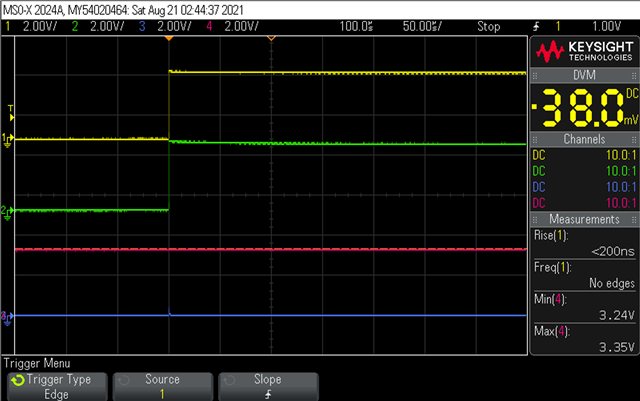
And oscilloscope capture of the "Yellow", "Blue", and "Green" signals:


Let me know if any more info could be useful.

  • Hey Joey,

    Is there a reason you're using the mux in this way or is there more that i'm missing? Looks to me like you have the IN pins tied to ground with the NO pin which means that you're only selecting the NC->COM connection ever. What's the purpose of a multiplexer here?
    Injection current is definitely possible via selected pins (See : [FAQ] Injection Current Control in TI Analog Switches). This current could be a cause of the initial bump. Does happen only after the first time switching after the device is turned on? The 806k resistor is very weak and it may not be allowing it to pulldown the line. It looks like there is a smart pull down feature on the TPS22917 that allows for the ON output to be pulled down when first powered on to keep it from floating. After it's power on sequencing is complete it's effectively floating. Could you disconnect the mux from the outputs of the TPS and see what the TPS output looks like independently?

    Also what's the supply voltage you're working with and could you scope the VCC as well for me? Current can be injected into the supply voltage which would shift your Ron and the VIH/VIL levels so i'm interested to see how the VCC looks relative to the timing of the transient you're seeing.

    Thanks,
    Rami 

  • Hi Rami,

    Thanks for the reply. To answer some of your questions:

    What's the purpose of a multiplexer here?
    Typically the "Blue" signal is connected connected to a microcontroller to handle switching however when debugging the issue, I noticed that even if I removed the microcontroller I was still seeing the issue so I didn't include it in the previous schematic. 

    Also what's the supply voltage you're working with and could you scope the VCC as well for me?
    Supply voltage is 3.3V. Seems like there is a momentary dip in voltage to around 2.9v in the VCC line (which is surprising to learn...) 
    Will provide scope captures and answer to other questions soon. 

    However at a high level I think I actually get around this weird configuration by just tying the NO pin to VDDS instead since the "Blue" signal swings to VDDS anyways. Do you think this could resolve the issue?


    Thanks,
    Joey

  • Hey Joey,

    Isolating the switching input from the I/O inputs will hopefully give us a better idea of what his happening here. In the scope shots initially, the blue input is between the VIH and VIL levels for 2.9V operation (approximating from the value in the datasheet between 3V and 2.7V operation) so we won't actually know what state it should be in and you may experience oscillation which looks like may be the reason why you're seeing parts of both signals present on the output. If we can isolate the blue input and have it switch properly in accordance with the VIH and VIL levels, I'd like to see the results from that.  

    Thanks,
    Rami 

  • Hi Rami,

    Here's what the scope capture looks like with VDDS (Pink Signal)


    When I remove the load connected to "Device_Power" I don't see this VDDS dip anymore and I don't experience the oscillation issue anymore ether. So perhaps it's the VDDS dip that is causing the issue. Although still surprising to me that the 10k pulldown on the "Blue" signal won't save me. 

    Here's what the scope capture looks like without load connected to "Device_Power"


    Thanks,
    Joey

  • Joey,

    Looks like there is some error happening with the VCC power that is effecting the switching. This would be the same setup with the NC and the IN3 connected correct? I would think that 10k should be fine, but if you have a stronger pulldown available, testing to see if that helps any wouldn't hurt. Bottom line though, it seems like the TS3A switch itself doesn't seem to be causing the issue and seems if we can resolve what is causing that VDDS dip, the problem should go away. The dip looks to begin before the switching even occurs, though. Is there some other part of the circuit on the same VDDS rail that aligns with this? Just looking to see what the 'trigger' for this error actually is; seems to occur randomly from the scopes. 
    I don't suspect that that dip is a normal phenomenon in the Vout of the TPS22917. What's the load you have on there typically? 
    I'm going to loop in the power management team responsible for this device to see if they have some insight on why this is happening and if we can prevent this dip. Maybe seeing the device power output would be helpful here too. I suspect if we stabilize the VDDS, the issues will be resolved. 

    Thanks,
    Rami

  • Hi Rami,

    Thanks for the quick replies.

    This would be the same setup with the NC and the IN3 connected correct? 
    Yes, same setup.

    I would think that 10k should be fine, but if you have a stronger pulldown available, testing to see if that helps any wouldn't hurt.
    Didn't try with a stronger pulldown yet but seems like if I use a gpio to keep this line to low it's also fine.

    Seems like if I toss a big cap on the "VDDS" (Near Vin of TPS) net the voltage dips to just 3.1V when I switch on the load and I don't noticed the switching error with the TS3A part anymore. The load is a high-ish power RF module. 

    Seems like the best solution would just be to stabilize the VDDS rail which I can do with a big cap. 
    Thanks for your insight here. Very helpful to scope the VDDS line.

    At a highlevel though, I still don't fully understand why even after the dip when VDDS recovers to 3.3v the "Blue" signal gets held at 1V. 
    Still would have expected it to finally go to 0.

    Thanks for your help,
    Joey

  • Hi Rami,

    Just circling back on this to see if you had any intuition on why the "Blue" signal continues to get held at 1V even after VDDS recovers to 3.3v.
    This would be helpful to understand so we could ensure more robust design in the future.

    Thanks,
    Joey

  • Hello Joey,

    How much capacitance do you have on your load of the TPS22917 device? If your inrush current is significant it could cause the supply to dip in voltage. You could add a capacitance onto your CT pin to control your slew rate, allowing for an inrush current your supply could handle without dipping in voltage. I don't see any way the TPS22917 would affect the blue signal. 

    Regards,

    Kalin Burnside

  • Joey,

    I'm not sure as to why the blue signal would be pulled up and held at 1V. It almost seems like a voltage divider is being formed somewhere, however, from the schematic, it seems as if it would be pulled down and since you switched the NO from blue to VDDS and the problem persisted, i'm not seeing where a potential would come from since only the pulldowns would be on the blue line.. How is the switching on the blue signal path happening?
    Is the GPIO that resolved this configured to have an internal pulldown? What's the value there and could you try replicated that externally?

    Thanks,
    Rami