This thread has been locked.

If you have a related question, please click the "Ask a related question" button in the top right corner. The newly created question will be automatically linked to this question.

MUX36D04: Minimising leakage currents

Part Number: MUX36D04

I need to measure a large number of high precision 100uA current sources using a mux to route each current source in turn to the measuring instrument. Achieving the lowest possible drain ON leakage of the MUX is essential. Maximum temperature will be 40C. The MUXD04 is the lowest leakage TI part I can find.

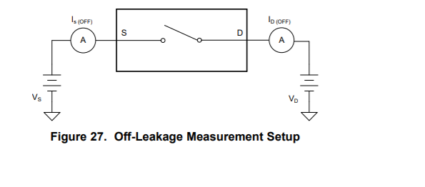
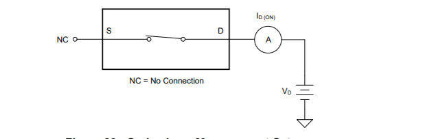
1) The datasheet shows graphs for leakage for Is+, Is-, Id+ and Id- but I can't find anything in the datasheet specifing the measurement conditions. In the case of OFF leakage is Is+ measured with the drain at VDD and Is- with Vd at  VSS (and vice-versa for Id+/-)? In the case of ON leakage is it where Vs = Vd = VDD / VSS respectively? The Id ON leakage is tthe most important in this application and the graphs show Id(on)+ to be considerably less than Id(on)- so I assume I would need to set the conditions similar to the former.

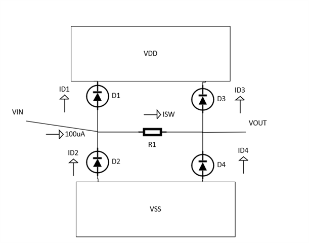
2) I assume that protection diodes are a significant source of leakage so I have the option to set the supply rails relative to the drain voltage - is there an optimal relationship? Eg. centering the drain voltage midway between the rails so that the top and bottom protection diodes see equal voltages? The source voltages will be at approximately 0V for the measured channel and 10V for the others.

3) By adding a second MUXD04 I could clamp the source voltages for the open switches to a bootstrap copy of the first mux's drain voltage so that all sources are at the same voltage, thus minimising the source - drain leakage of the OFF switches. It would also allow the MUX supply voltage to be set to the minimum (10V).

The off leakage of the extra switch connected to the measured channel's source will add to the error but a) source off leakage is significantly less than the ON draIn on leakage and b) option 2 above may be more effective, perhaps, since all sources see the same voltage as the drain?

4) Is there a better / more suitable part that I should consider?

  • Hi Tony,

    1. Our test set up for off leakage is shown below:

    On Leakage:

    For your specific question on ID(ON)+ vs. ID(ON)-   if you look to the on leakage measurement setup only VD is connected - but the measurement conditions in the data tables specify a +VD and a -VD value - where ID(ON)+ has VD = +VD (whatever is specified in the datasheet) and ID(ON)- has VD = -VD. However I will say that input voltage is a very small part of the total leakage as its mainly temperature dependent (typical input voltage has polynomial effect on the leakage (typical linear but can be higher order) compared to the temperature dependency which is exponential. ID(ON)+ is most likely going to have less leakage present at 40C based on the graphs on the datasheet as ID(ON)- has started to trend downward at that point in both graphs that we have in our datasheet.

    2.You are correct -the protection diodes are the main source of the leakage. As for a good point to go into the rail to ensure less leakage - its kind of hard to tell to be honest due to the temperature dependencies - however if you look at a simple model below you can kind of see what is affecting the leakage (on leakage)

    To help simplify this use the following equations

    All of the diode currents can be found with : Id = I_sat * (e^(Vd/(n*Vt)) - 1) (the shockley equation).

    Assume all diodes are the same - (assume Vt, I_sat, and n are constant in all 4 diodes - Vd will be different on all the diodes)

    t = Vt * n

    k = I_sat

    a = VDD - Vin

    b = Vin - VSS

    c = VDD - Vout

    d = Vout - VSS

    ID1 = k * (e^(a/t) - 1)

    ID2 = k * (e^(b/t)  - 1)

    ID3 = k * (e^(c/t) - 1)

    ID4 = k * (e^(d/t) - 1)

    ISW = 100uA + ID2 - ID1

    Vout = VIn - ISW * Ron

    So the best bet is to try to cancel out leakage by making ID1 = ID2 and ID3 = ID4

    setting ID1 = ID2

    k * (e^(a/t) - 1) = k * (e^(b/t)  - 1) -> which simplifies down to a = b which means ideally VDD - Vin = Vin - VSS -> Vin = (VDD + VSS)/2 and that theoretically will cancel some of the leakage but there will be some at the output due to the voltage drop - however this shouldn't be a huge difference. That being said real devices may have very small differences in saturation currents of ideality factors of the diodes and these slight differences can cause some deviation from this approximation - but essentially its hard to completely eliminate all diode on leakage as there is a voltage drop in-between sets of diodes. 

    3. So in terms of leakage you are correct - by forcing all the source pins to the same voltage (should be about halfway between VDD and VSS for best results) the drain leakage is larger as absolute worst case in the -40C to 85C range (you are at the lower end so it is extremely unlikely it would go this high) is +/-150pA  compared to the +/-500pA of the on leakage - so if there are two muxes you could see a worst case of +/-300pA which is still lower than the drain on current max. But I'd like to stress that this is worst conditions and since you aren't close to 85C you should get better performance.

    One thing to note however is that if you use this device in a differential signal application you can get lower leakage - I assume its single ended by the numbers you are looking at but if it is differential please let me know. 

    4. In this voltage range that you are looking at - which I assume is mid-voltage and/or dual supply  than yes you are looking at probably the best solution as our upgraded parts in this portfolio do have a bit more leakage current so I think you are looking at the correct part.

    If you have any other questions please let me know!

    Best,

    Parker Dodson

  • Hi Parker,

    Thanks for the very comprehensive and helpful response. I missed the Id(on)+/- conditions in the datasheet because I was looking for those specific terms in the tables; I don't think it's as clearly spelt out in the D/S as it could be, although note (1) (which I overlooked) does gives a clue. Anyway the applicable voltages from the D/S are +/-10V for Is(OFF) and Id(OFF) when operating from +/-15V supplies and 1V and 10V when operating from a 12V single supply.

    I'll have to experiment to see how low a leakage can be achieved by ensuring the best operating conditions but I'm reasonably hopeful I can reach the D/S typical values from what you have said without doing a lot of (expensive) select on test!