Because of the Thanksgiving holiday in the U.S., TI E2E™ design support forum responses may be delayed from November 25 through December 2. Thank you for your patience.

This thread has been locked.

If you have a related question, please click the "Ask a related question" button in the top right corner. The newly created question will be automatically linked to this question.

TMUX1208: TMUX 1208 Driving a relay-Circuit Review.

Part Number: TMUX1208
Other Parts Discussed in Thread: SN74CB3Q3251

Dear Team,

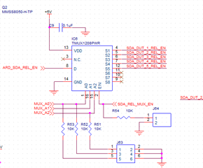
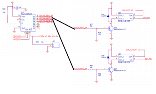
I am using TMUX1208 for driving a relay. The control signal is coming from an Arduino. Below is my circuit.

May I know the below circuit is fine or not?

Do I need to GND the unused pins.Now I put it as Do not connect

Regards

HARI

  • Hey HARI,

    The 1208 circuit looks fine. For the unused pins you may leave the unused signal pins floating. Please see TI Precision Labs - Switches and muxes: Can I leave unused pins floating?

    Thanks,
    Rami

  • Hi Rami,

    Thank you very much.

    I have 2 questions

    Qusetion 1

    May I know the on capacitance of  TMUX1208?In datasheet, I can see the CSON of TMUX1208 it is 85pF. CDON of TMUX 1208 is not there.

    Total on capacitance is sum of the two.Please correct me if I am wrong.

    May I know the on capacitance at 100Khz

    Qusetion 2

    To avoid any confusion during Power on I am planning to connect pull-down resistor to address
    and enable line. The mux is controlled by an Arduino Nano.
    Below is my circuit. May I know 10K is fine or not. (As per suggestions from Higher management :) )

    One more question,

    Do we really need pull-downs for Mux? As per my knowledge floating is fine.

    Please correct me If I am wrong.

    Regards

    HARI

  • 1. When the switch is on, S and D are connected; the specified capacitance is for the channel. (The specifies CSON and CDON apply to both devices.)

    2. CMOS inputs must never float. If the Ax and EN signals are not driven at all times, you need pull-ups or pull-downs. (You are allowed to drive the Ax and EN pins even before the TMUX has powered up.)

  • Hey HARI,

    So for your first question, you'll see in the datasheet it's actually listed as both CSON and CDON. CSOFF and CDOFF are different but when the switch is on, the source and drain are the same, so the capacitance is shared. Across frequency, this shouldn't change.

    I believe you're talking about the logic control pins. These should never float so a pull down would be recommended. You don't necessarily need pulldowns if the state is being driven consistently by a source but it would be good practice to have one. If the signal isn't being driven, there will be an unknown state on the logic which wouldn't allow for proper switch selectiong. The 10k resistor should be fine. See Choosing an Appropriate Pull-up/Pull-down Resistor for Open Drain Outputs.


    Thanks,
    Rami

  • Hi Clemens,

    Thank you...

    Regards

    HARI

  • Hi Rami,

    A0, A1, A2, and EN are not driven constantly in my application.

    Thank you for confirming 10K is fine

    Regards

    HARI

  • Hi Rami,

    One more question

    I can see that MUX with low output capacitance has a large Ron.

    May I know is this an expected behavior. If yes may I know why?

    Regards

    HARI

  • Analog switches are implemented as transmission gates, which consist of two MOSFETs. The gate of a MOSFET essentially is one half of a capacitor; the charge on the gate causes the source-to-drain channel to become conductive. Lower Ron requires a larger charge, which implies a higher capacitance.

  • Hi Clemens,

    Thank you ...

    So Lower Ron means higher output capacitance and vice a versa

    Regards 

    HARI

  • Hey HARI,

    Typically yes this is the case. You will see some devices with an internal charge pump that can keep the on resistance low while maintaining low on capacitance. The signal pass through isn't limited from rail to rail (0V to VCC), as well. The tradeoff here is that the draw more current to operate. 
    For the most part, TI muxes have transmission gate architecture, which will keep the on resistance low but the capacitance will be the trade-off. As mentioned, these are typically inversely related. The power consumption is greatly reduced as well here. 

    Thanks,
    Rami

  • Hi Rami,

    Thank you...

    May I know TI has any 1 to 8 MuX with charge pump?

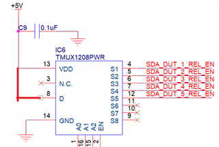
    I decided to connect D to Vcc so that I can use the microcontroller pin for other applications. Below is my Circuit.I Hope 10K Pull up if fine.

    May I know your comments?

    Regards

    HARI

  • Hey HARI,

    The SN74CB3Q3251 is an 8:1 mux with a charge pump. 

    I wouldn't recommend tying you I/O line with the same VCC supply to power your device. With the decoupling cap, it may resolve any noise but there is a chance that when switching, the current draw will cause performance deviations.

    If you're running into an issue of a loss of GPIO space, a multiplexer could help resolve this as well Choosing the Right Multiplexer for MCU Expansion 


    Thanks,
    Rami

  • Hi Rami,

    Thank you very much.

    Question-1

    SN74CB3Q3251 is 3.3V Mux.

    May I know anything with 5V Vcc.

    Question-2


    "I wouldn't recommend tying you I/O line with the same VCC supply to power your device. With the decoupling cap, it may resolve any noise but there is a chance that when switching, the current draw will cause performance deviations."

    For avoiding this can I use a Separate 5V rail which is different from that powering the IC?

    Question 3

    May I know is there any problem in connecting the MUX_EN(coming from Arduino) signal to D also.

    Regards

    Hari

  • HARI,

    Question 1)
    The VCC is 2.3-3.6V but the voltage that can be applied to the I/O's is up to 5.5V independent of the supply so this will still work for 5V operation. So you can use a lower supply and still get to 5V on the I/O.

    Question2)
    You certainly can try and you very well may not see any problems. I typically don't recommend driving an actively changing source from your supplies that you're powering your components from just to ensure that a constant source is maintained since shifts in the supply will affect most device performance. 

    Question3)
    There shouldn't be a problem here besides added capacitance may slow down the signal a tiny bit. You'll also want to make sure that your logic is sound. That's to say, if you're using a device that has active low enable, you won't be able to turn the enable on and pass a signal at the same time, since the high state will put the device in Hi-Z.

    Thanks,
    Rami

  • Hi Rami,

    Thank you very much.One more question. Please don't feel bad.

    Can I directly connect D to Vcc without any pullup

    Regards

    HARI

  • Hey HARI, 

    A pullup would be recommended. You'll want to limit the current going into the device below the abs max source or drain continuous current (+-30mA). TMUX1208 has a low Ron so the current would fry the chip without the resistor. 

    Thanks,
    Rami

  • Hi Rami,

    Yes got it.Since it is going to base of a transistor and base current is set to 4mA and a 680ohm is already present in the board I am planning to keep a pull up 

    of 200Ohm.

    Regards

    HARi