Dear ,
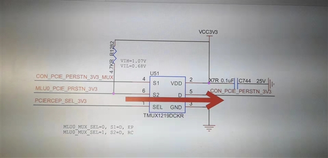
as below , there is crosstalk issue between S1 and S2;normal pin 6 S2 control pin 5 D output ,SEL is 3.3V; but When pin6 S2 oscillates, pin4 S1 is affected; could you give me any advise ,many thanks~
This thread has been locked.
If you have a related question, please click the "Ask a related question" button in the top right corner. The newly created question will be automatically linked to this question.
Dear ,
as below , there is crosstalk issue between S1 and S2;normal pin 6 S2 control pin 5 D output ,SEL is 3.3V; but When pin6 S2 oscillates, pin4 S1 is affected; could you give me any advise ,many thanks~

Hey Cooper,
I believe there is a small typo here on "When pin2 S2 oscillates", I believe you meant pin6. I've edited your question to fix this.
Could you provide more information on what the crosstalk looks like and what frequency and voltage you're working with? If you could get a screen shot of what you're seeing, it would be useful. The crosstalk is spec'ed in the datasheet and we provide a figure (figure 5) of this across frequency. You'll see that higher frequencies you may see some, so knowing some information on the signal being applied would be useful as this could be the impactful to your setup.
Thanks,
Rami
Hi Rami:
you are right ,my mistake;
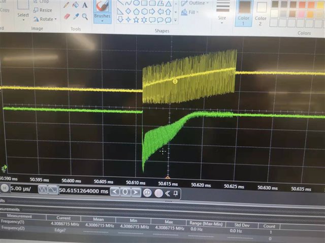
the wave is below, the voltage is 3.3V ,when S2 is rising, there are some oscillations, meanwhile, S1 also has crosstalk ;
Hi ,
add frequency = 15M condition, figure 5 refered 15MHz , in fact S1 crosstalk is much bigger as above wave;
Hey Cooper,
Could your provide more information on the expected waveform? Is the oscillation on S2 expected? Looks like the oscillation may be in the ns range so this may be an issue.
I see in your schematic that S2 is tied to VCC. Could you drive S2 from a different source and see if that resolves the problem. If not, a probe of VCC could be done to see what is happening.
A screen shot of S1, S2, D and VCC would be useful here. Could you label the signals and provide the voltage scaling of each to help me understand what's happening better? I'm assuming that the control logic isn't changing but if it is, including that in the scope could help determine what is happening. The actual rising shouldn't cause crosstalk since it's on the slower side but the actual oscillation within the rising waveform is significantly faster, so this could be the source of the problem. I'm looking to see how the VCC looks when the rising edge occurs.
Thanks,
Rami
Hi Rami:
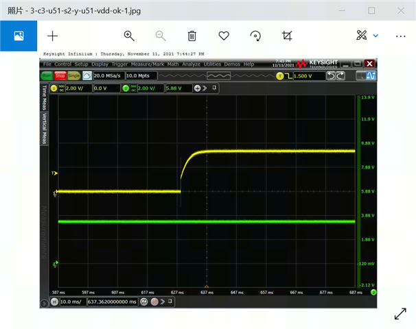
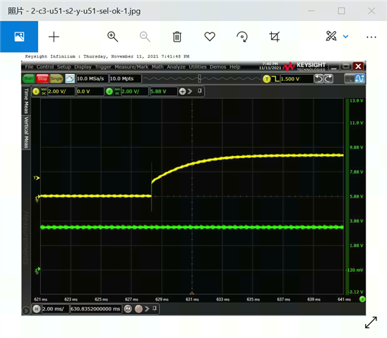
VDD & Sel voltage I test are all ok ; the Sel and S2 waveform is 1 as below , the VDD and S2 is 2 as below;
1
2.
Hey Cooper,
Was this test done with VDD tied to S2? Looks like there is a bit of noise on the VDD, which I believe is the green waveform on the 2nd scope, that follows the noise on the S2 waveform.
Thanks
Rami
Hi Rami:
so, the solution is ? the crosstalk between S1 and S2 is related to Vdd noise ?
Sorry, I checked and confirmed , the Vdd and S2 wave image is as below, no noise ;

Hello Cooper,
It may be due to the noise on the VDD which is why I wanted to look at the scopes and was looking to see if you could provide an S2 input from a different source.
Could you drive S2 from a different source and see if that resolves the problem
Have you done the above recommendation or is the Vdd still tied to the S2 input here. Sorry ,I'm not sure if i'm understanding correctly but is the noise gone but the crosstalk still there or is this issue resolved now?
A screen shot of S1, S2, D and VCC would be useful here
Sorry I wasn't more intentional on what I was asking here. Having these inputs in different screenshots isn't terrible helpful. If the crosstalk is still there, can you provide an image with VDD, S1, S2 and D on the same scope at the same time?
-Rami
Dear Rami:
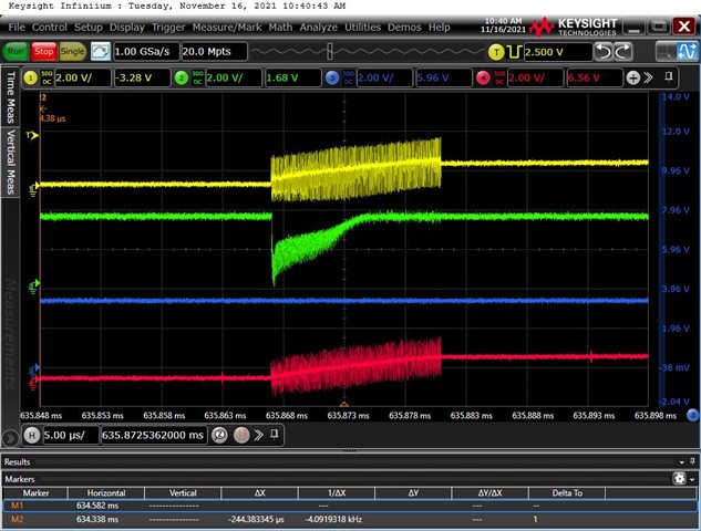
A screen shot of S1,S2,D and VCC as below, blue is Vcc, red is D; you see, the vcc is clean ,no noise; the S2 driver Vdd is only one source on the board; so could not change different source, but according to wave as blow, there is no noise in Vcc ;
Cooper,
Thanks for sharing this. The oscillation is not present in the waveforms with only VDD/SEL and VDD/S2 but suddenly appears again when you're probing S1 and S2 together. Did you change anything in the test setup besides which inputs you're probing?
No oscillation:

Oscillation:

If the oscillation and crosstalk is only appearing when you're probing both S1 and S2, I would suspect something is happening with your test setup/probes. How long are the probes?
Looks like S1 is connected to the PCIE. Could you disconnect and try and isolate the mux alone during switching?
Additionally can you share any layout you have? How are you connecting these signals? Providing proper spacing between the traces and keeping them as short as possible is recommended in the layout.
Thanks,
Rami
Hi Rami:
Oscillation is always exist , only oscilloscope scan time setting question;
so your mean maybe layout issue is referred to crosstalk ?
Cooper,
Oscillation is always exist , only oscilloscope scan time setting question
This looks like you slowed down the rise time of the device quite a bit here too. The screen shots with just the VDD and S2 waveform the rise time is almost 10ms, while in the last screenshot the rise time is roughly 5microseconds. Can the driving output support this rise time?
The oscillation looks like it's ~2V. This is extremely high. Higher than you would expect from crosstalk so i'd like to look at the setup instead and you should look into whether your driving source can drive at the speeds you're aiming. Can you repeat this on different chips/boards or is this only on one TMUX1219?
so your mean maybe layout issue is referred to crosstalk ?
Yes, the layout can definitely influence the crosstalk. Is it possible to provide this?
Another point of clarification I'd like is about the VCC line. If you're tying the VCC and S2 together, how is VCC clean but the S2 line not? You should be seeing close to the same on both lines if you haven't driven them from different sources.
Thanks,
Rami