This thread has been locked.

If you have a related question, please click the "Ask a related question" button in the top right corner. The newly created question will be automatically linked to this question.

SN74LVC1G17-Q1

Other Parts Discussed in Thread: SN74HCS125-Q1, SN74HCS126-Q1
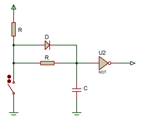
I want to design a hardware debounce circuit and I need help with some calculations.

1: How I can figure out the bounce time required for a switch prior to physical testing?

2: I noticed that some circuits use R2. Is there any thumb rule to select that value?

3: I have to connect three switches so can you help me to choose a Schmitt trigger?

4: Selection of Diode, What parameters should be consider while selecting a diode? or simple General-purpose diode will do the job?

https://www.ti.com/lit/an/scea094/scea094.pdf
  • 1. The bounce time should be specified in the datasheet.

    2. That depends on the purpose of R2. If you want to limit the current, you need to know what limit you want.

    3. There are devices with multiple channels, e.g., SN74HCS125-Q1 or SN74HCS126-Q1.

    4. Any small-signal diode will work. The usual choice is the 1N4148 or some SMD equivalent.

  • Let's say, I choose top R = 100K and C = 0.1uF to get the 10mS debounce time. I also add a diode to quickly charge the capacitor bypassing bottom R.
    I need some equations or suggestions for the bottom R-value. Somewhere, I read that it should be 1/10th of the above R value.
    Thanks

  • R2 slows down the discharge of the capacitor. Its size depends on how slow you want the falling edge to be, or how much you want to limit the current spike of the discharge. In the absence of any other information, 1/10th of R1 sounds OK.

    The diode makes the charging time independent from R2. You could just as well make R1 smaller by the same amount and drop the diode, and with 1/10th of R1, the difference does not really matter anyway. (The diode would make sense only if R1=R2.)

  • so if i need 20mS charging and discharging, i should keep both resistors the same keeping the diode. Right?

  • For example,
    C = 0.1uF, R = 200k ohm.
    What about hysterious value of  Schmitt trigger? Shouldn't i consider that value for selecting capacitor charging and discharging values?

  • Yes, R1=R2 with the diode is also reasonable. (But in practice, the capacitor discharging much faster than charging is not a problem.)

    The hysteresis (and switching thresholds) of Schmitt-trigger inputs are not very well specified. But you have large tolerances on the capacitor anyway, so this is usually not a concern.

  • Hi Ali,

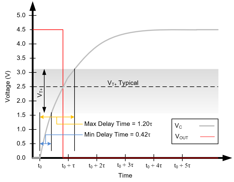
    I built this graphic a while back to help show how the thresholds of a Schmitt-trigger buffer / inverter can affect the delay time of an input signal:

    The red line shows the typical output transition time, and the min/max delay values show where the output could possibly switch based on the datasheet limits.

    This was developed for a particular device, however you could apply the same concepts to any ST device -- you just need to know the RC capacitor charge equation and the threshold limits, then you can solve for the min/max delay times as a function of time constant (tau) pretty easily.

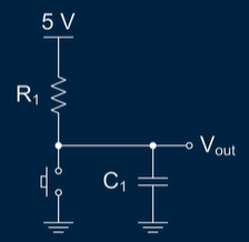
    Generally speaking, with a debounce circuit, it's not worth going into all this. It's much better to just apply a value that you know won't 'feel' bad to a human pressing the button, so I just select C = 1uF and R = 10k (tau = R*C = 10 ms), which works well in the vast majority of cases. In the event that you're getting errors due to bounce, it's always easy to change R to a larger value.

    Here's the circuit I generally will use (image from Debounce a Switch:

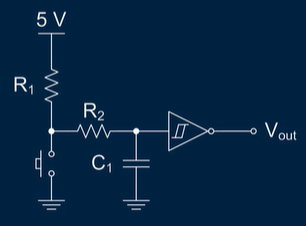
    I've never run into problems using this, but theoretically the two-resistor solution you have is better (which is also covered in that video).

    If I were to use the two-resistor solution, I would set C1 = 0.1uF, R1 = 10k, R2 = 100k, which means the rising and falling edges would be fairly similar (only 10% difference).

    Personally, I would not use a diode for this circuit because of the added cost and lack of any real benefit for normal operation.

  • Thanks for your great explanation. I really appreciate it. I was looking for exact same explanation that you provided. I selected this ST(ST) and I guess everything is clear now.

  • Hi Ali,

    I'm glad that I could be of help. If you feel like this thread is resolved, please mark the appropriate answer (I believe it's a green button) -- this will help people in the future find this thread if they have a similar question.