This thread has been locked.

If you have a related question, please click the "Ask a related question" button in the top right corner. The newly created question will be automatically linked to this question.

TMUX1108: Drift under room temperature

Part Number: TMUX1108
Other Parts Discussed in Thread: TMUX1109

Hi Team

My customer is considering TMUX1108 for temperature control board application but has concerns regarding the resistance drift under the room temperature.


The actual operating temperature of the board occasionally drops to -20 degrees Celcius due to the TEC, while sometimes it rises to 20 degrees Celcius.
I checked the datasheet and found the temperature drift chart for high-temperature applications, but there's no specification regarding the temperature that's lower than 25 degrees Celcius.
Could you help provide some information in such regard?

Regards

David

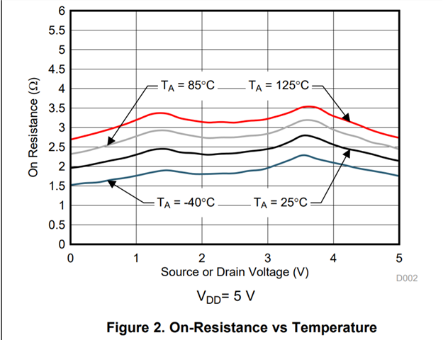
  • In figures 2 and 4, the lowest curve is for −40 °C.

  • Hi David,

    The on resistance of the device changes w.r.t. input voltage from pin to ground, temperature, and voltage supply. 

    For your case of -20C and 20C operation this is going to be best captured by figure 2 (VDD = 5V) and Figure 4 (VDD = 3.3V). Please let me know if the voltage supply is lower than 3.3V.

    Using figure 2 as an example:

    From this we can gather a few equations through regression tools using Excel or similar programs. The range of operation for your application is going to in-between the blue (-40C) and black (25C) lines Using these lines you can approximate the resistance at a specific temperature + input voltage.

    However I am curious on the use of this device and where it is being placed in the signal chain. Is this device feeding into a high impedance load such as an ADC or operational amplifier? I ask because that is a pretty common use case of this device and generally in those types of applications some parameters of the multiplexer really don't make much of a difference such as on resistance. 

    If you could let me know a few things about the application I should be able to point you, and your customer to some of our design collateral as well as have some implementation tips. Essentially the big things I want to know are:

    1. What is the output of the mux going towards, i.e. what is the load of the mux? 

    2. What supply voltages are being used?

    3. Where is the input signal coming from, is it a sensor or something else?

    Please let me know as if I am correct about the application you are trying to complete we do have more material that could be helpful in these types of designs.

    Best,

    Parker Dodson

  • Hi Parker

    Much appreciate the response!

    It would be great if you could provide some reference designs or other collaterals, as the customer is looking for the ADC solution as well. Thanks!

    For you questions:

    1. The MUX is used for thermistor's application, which means the input of the MUX would be thermistor and the output would be the ADC.

    The customer's goal is to switch 160 thermistors within 100ms(using multiple MUXs and ADCs)

    2. We don't have the information regarding the supply voltage.

    3. The input comes from the thermistor

    I think the temperature drift of 1108 would be fine since the thermistor's value ranges from 5k to 500kohm, but since the customer's also looking at ADG7421f、ADG714, it would be the smaller the better.

    Regards

    David

  • Hi David,

    Thank you so much for the extra information! 

    We have an application note on tips on how the multiplexer can be integrated into data acquisition systems - so it is a generalized guide on how to view a mux when paired with an ADC. Here is the link: https://www.ti.com/lit/pdf/SCDA031

    So when working with a thermistor to ADC measurement you really want a device that has low leakage currents (which this device has very low leakage (pA range) and the typical is slightly lower than the competition with typical off leakage of 3pA compared to 10pA. These leakage currents cause voltage offsets at the point that the ADC is trying to read. With low leakage the 1108 is a great option as it will cause a very small voltage offset to occur. 

    I do think you are correct that the resistance of the variance of the switch is pretty much negligible. Essentially you have a pretty high source impedance and a high load impedance (ADC's input impedance is going to be >> than multiplexers on resistance) is going to lead to very little attenuation across the mux. Most likely this small deviation is not going to cause any discrepancies in the measurement based on what has been provided. 

     The TMUX1108 is probably the best 8:1 with all the considerations as it is a perfect part for ADC input expansion with sensors like thermistors with its low leakage currents, decent channel performance, and ultimately the smallest 8:1 multiplexer that we have when used in the RSV package. A nice feature when using high precision multiplexers like this is that you don't need to do much besides drop it into the design because it is very close to an ideal switch. 

    I don't see a problem cascading the multiplexers to create essentially what is essentially a "160:1" multiplexer. But one thing to consider to save on space is to use the TMUX1109 as well. This is a 2 channel 4:1 and can be used at the first stage of the design to reduce the total number of devices. Please see below for a basic guideline.

    This will be less parts and both parts have extremely similar specs than if you just use the 1108 + each thermistor is going to see the same # of switches before the ADC. This is relatively low speed so some of the issues with cascading shouldn't be that much of an issue. There are 8 different control lines needed as 160 is an 8 bit number and these are GPIO controlled devices. The transition time should be in the nanoseconds so there should be 0 issue with the time needed. 

    The only possible concern is if the ADC needs to be driven - the multiplexers are passive so they don't drive signals - if drive strength or buffering needs to happen before the ADC the amp can be placed at the end of the mux chain leading into the ADC - as this is also a common use case of multiplexers in analog front ends similar to this.

    If you have any other questions please let me know!

    Best,

    Parker Dodson