This thread has been locked.

If you have a related question, please click the "Ask a related question" button in the top right corner. The newly created question will be automatically linked to this question.

TMUX1109: TMUX1109PWR application circuit for switching between two inputs

Part Number: TMUX1109
Other Parts Discussed in Thread: TMUX7219,

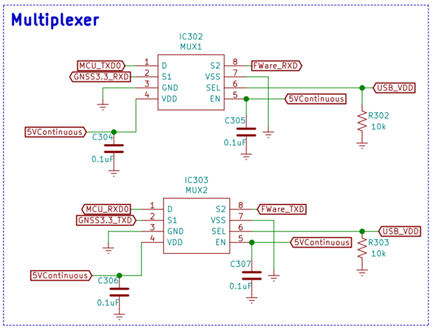
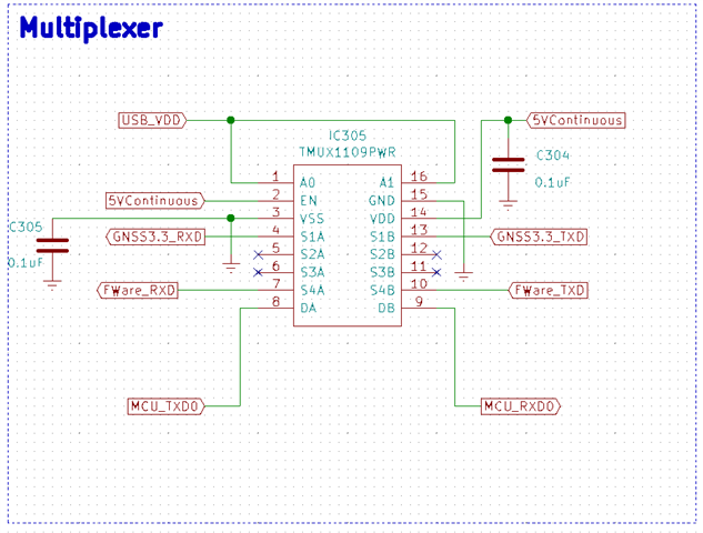
I am using this 4-channel multiplexer to switch my UART connection to an MC upon insertion of a USB for firmware uploads.  Previously I was using two distinct 1 channel multiplexers but decided to consolidate the design to use just one. 

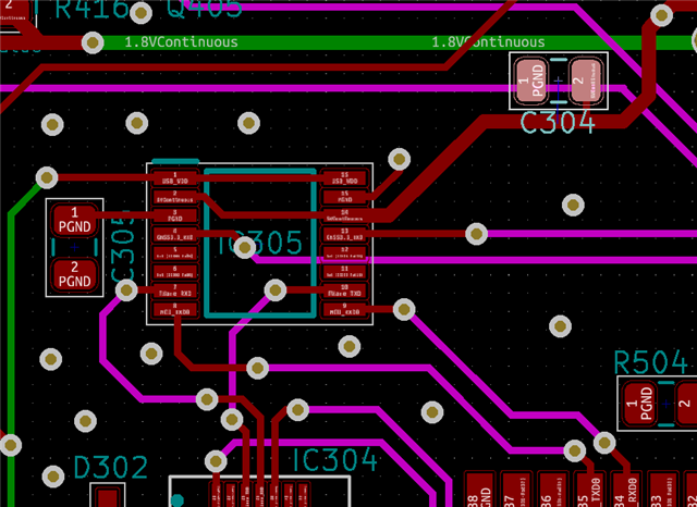
I am just testing out the PCB and noticed that I cannot perform a firmware upload.  My PC is recognizing the UART bridge chip but cannot connect to the MC.  My thinking is it is likely that either the application of the multiplexer circuit is incorrect or my MC is dead on arrival.  I have seen the latter before, but if someone could take a second look at the multiplexer circuit and let me know if they see anything crazy that would be awesome.
  • Hi Alex,

    The only thing on the schematic that I see is that C305 is unnecessary since VSS is grounded in this application. However I don't think that would cause performance issues. We also generally suggest terminating floating I/O pins - but UART is pretty slow so it probably isn't causing much issue. 

    So Overall I don't think the multiplexer is causing any issues - as long as USB_VDD is high enough to turn on the pathways / off the pathways when required it shouldn't be an issue. It might be beneficial to test that voltage just to see - I doubt that is the issue, but its generally a pretty easy thing to look at. Also probing both sides of the switch to see if you are getting the signals expected would be another thing to see if the mux is the issue. 

    If you have any other questions please let me know!

    Best,

    Parker Dodson

  • It turned out this circuit worked alright for the application, as your expectations indicated.  There was a small soldering issue elsewhere.  Thank you for helping direct my focus.

  • Hi Alex,

    No problem, I am glad I was able to help out!

    If you have any other questions please don't hesitate to reach out!

    Best,

    Parker Dodson

  • Hey Parker I did notice something strange that I think you hinted at being a possibility earlier.  If my GNSS/cellular modem is up and running while I attempt a firmware upload on my main MCU.  This is connection S1A/B  My firmware uploads fail; however, if I power down the modem and attempt an MCU firmware upload everything goes smoothly.  Is this because of the unterminated UART lines? 

    This response was noticed only after adding the multiplexer.  

  • Hi Alex,

    What connection is failing? 

    The schematic says that the firmware is on S4A/B  (When USB_VDD goes high these signals will be routed to DA/DB respectively) but S1A/B are the GNSS signals. 

    Is the switch not switching to S4A/S4B when both A0/A1 = Hi ?

    Sorry, but if you could please clarify that would be helpful!

    However I don't think its the termination for UART - that being said, to verify what is the data rate you are working with, what PHY are you using for UART, and what is the length of the transmission line/cable. Essentially the terminations are for preventing signal reflections - UART is generally pretty slow and so it would have to be a long cable/transmission line for the signal reflections to really start causing issues. Adding a termination ~ characteristic impedance of the transmission line is a good place to start - the PHY standard used also can suggest or determine what cables can be used. 

    However; one thing I do notice that I missed on my first pass through - are A0/A1 grounded when the USB cable is removed? 

    Please let me know!

    Best,

    Parker Dodson

  • Parker, I apologize for the lack of clarity.  Below is some more specific information.

    The firmware upload is connected to S4A/B the GNSS/cell module is connected to S1A/B.  When the gnss module is powered on my firmware uploads are failing to the MCU.  It seems that a connection is still detected by the PC and MCU but I am getting errors and uploads are unsuccessful.  So I power down the gnss module and firmware uploads go fine.  The rate is 115200.

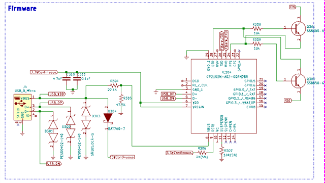
    The GNSS UART lines are internal to the PCB about 200mm total length and the cable for the firmware uploads is about 2ft.  This same cable and setup were used prior to the addition of the multiplexer and firmware uploads could be completed with the GNSS module on.  The firmware upload circuit is below but basically there is a USB to UART bridge IC.  So I connect to a USB port on my PC.

    The ground is an excellent question.  The VDD line is pulled down to GND by a 10k resistor.  This is its connection to GND.

  • As a side note I wanted to mention that prior to using this multiplexer I was using two TMUX7219DGKR multiplexers in the circuit below.  Firmware uploads weren't failing but the cost was higher.

  • Hi Alex,

    Thank you so much for the clarification!

    This is definitely a strange issue - especially with regards to the TMUX7219 working in this application.

    Is it possible to get a scope shot of the output during a firmware update attempt? The reason I am asking because I want to see if there is frequency related leakage. 

    I think there are 2 possible issues:

    1. Essentially what could be happening is that signals can leak into other inputs (cross-talk), or through an off channel. This is primarily frequency related. The TMUX1109 should perform better in terms of off isolation and marginally better in leakage current (both the 7219 and 1109 have pA typical leakage values). The only real advantage the 7219 has is that is performs slightly better in terms of cross talk -> the 1109 also has all the signals routed through one package increasing the odds of cross talk occurring. Also I am not sure how the layout changed from the 7219 to the 1109 but that could also increase possibility of cross talk. Getting a scope shot with the firmware update failing due the GNSS signals are active on the deactivated pins and then a scope shot of the firmware update succeeding (with the inputs also scoped in both situations) this will allow me to see if there is frequency dependent cross talk happening in the signal.

    2. Signal reflections due to unterminated pins. I don't think this is super likely, but a major difference between this design and the old design is that the current design is using unterminated S pins. If these aren't terminated with 50 Ohm resistors to ground they could possibly cause reflections that negatively affect the signal chain. This increases a bit due to the 2 Ft. cable -> and if this is the reason why there are failures it is most likely not the fundamental frequency of the signal but a higher harmonic..

    Essentially those two groups are where problems could be are the differences between the 1109 and 7219 

    1. Frequency dependent leakage from 1109 and/or new layout with 1109

    2. Signal Reflections due to unterminated S pins on 1109.

    One more thing to note is that the 7219 is also lower bandwidth so it could be attenuating higher frequency harmonics while the 1109 could be passing them through and causing reflections as well. I don't know if this is causing the issue but it is also a difference between the parts.

    If you could get me a scope shot to see if the output is being polluted by one of the inputs and it should be able to show if that is where the problem lies.

    Please let me know!

    Best,

    Parker Dodson

  • Hey Parker 

    Excellent summary of the potential problems.  I have read through it a few times now, it took me a little while to get back because I wanted to make sure of what I was reporting because it seems to me to be pretty clean signals.

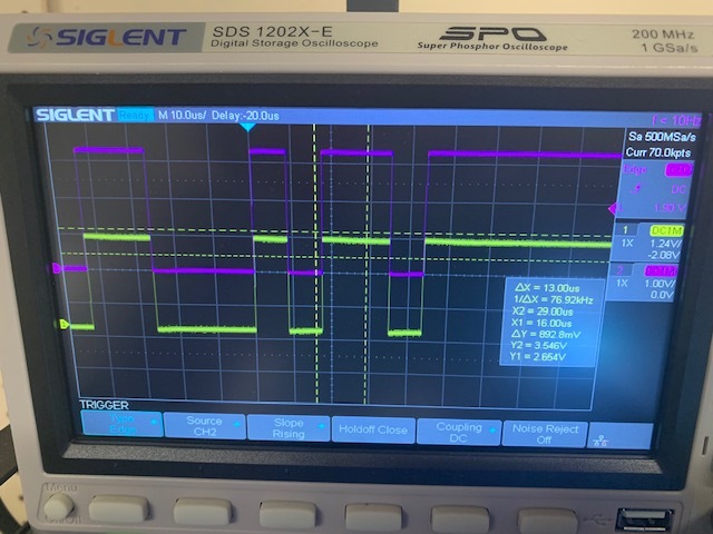
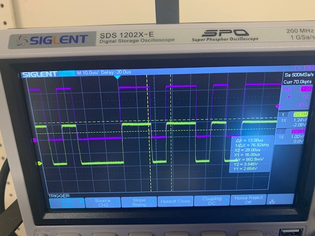
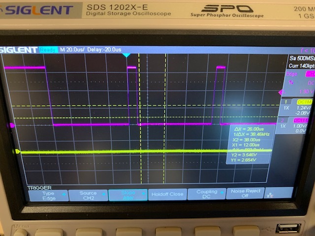
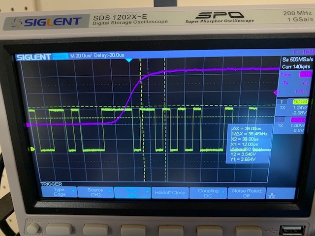
    I took some scope shots during firmware uploads and noticed that GNSS TXD is not really active.  Except about every 3s the model attempts a boot while the MCU is uploading firmware.  This results in the GNSS TXD going to high voltage for about a 1s before falling back to low voltage.  Although when I am able to do firmware uploads successfully, with the GNSS module powered down, this activity is not present.  I didn't see any signs of cross-over.  Let me know what you think!

    S4B and DB


    S4A and DA

    GNSS and Firmware RXD (S1A and S4A respectively)

    GNSS and Firmware TXD (S1B and S4B respectively)

  • Hi Alex,

    Those signals do in fact look very clean - so I don't cross talk is an issue and would assume the layout is fine. To confirm you didn't notice a difference between the outputs of the mux when the GNSS was active and when it was not correct? Because that's what it seems like between the two parts.

    That just makes me think that ultimately its not the multiplexer directly unless some transient event is occurring that isn't being captured that is causing an issue. I do think this is unlikely though.

    Have you tested more than 1 board - or tested with a different MCU unit?  I am asking because it just doesn't look like the mux is impacting the signal very much if at all - which is to be expected with the 11xx line of parts since they are our highest precision low voltage analog switches, and I just want to completely rule out an MCU issue that could have possibly happened in the interim between changing the TMUX7219 out for the TMUX1109.

    Please let me know!

    Best,

    Parker Dodson