A related question is a question created from another question. When the related question is created, it will be automatically linked to the original question.
If you have a related question, please click the "Ask a related question" button in the top right corner. The newly created question will be automatically linked to this question.
For some reason - this drawing does not include an example land - pattern and solder mask details - however other similar UQFN's do - and the rules that they have can be transcribed to the above drawing.
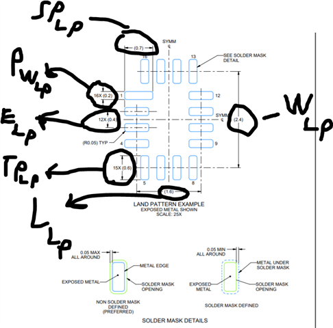
Using the 16 pin as an example - take a look at the package drawing , land pattern/solder mask (pattern and mask are same dimensions - please follow solder mask details on the 16pin or 10pin UQFN as it will be the same for the 12 pin as with the 1072) (shown below):
Package Drawing:
Variables:
L = Length = Typical 1.8mm
W = Width = Typical 2.6mm
TP = Top and Bottom Oriented Pins Length = Typical 0.4mm
TP_LP = Top and Bottom Oriented Pins Length of Land Pattern= 0.6mm
SP_LP = Side Oriented Pins Length of Land Pattern = 0.7mm
PW_LP = Pin Width of Land Pattern = 0.2mm
E_LP = Pitch of Land Pattern = 0.4mm
If you look at how these dimensions change - its actually standardized between pin counts (look at the 10 pin package and the same pattern will emerge) - which is the following:
L_LP= Length of Land Pattern = L - 0.2mm
W_LP= Width of Land Pattern =W - 0.2mm
TP_LP= Top and Bottom Oriented Pins Length of Land Pattern= TP + 0.2mm
SP_LP = Side Oriented Pins Length of Land Pattern =SP + 0.2mm
PW_LP= Pin Width of Land Pattern = PW
E_LP = Pitch of Land Pattern = E
TMUX1072 Land Pattern Dimensions
Which when we plug that in for the TMUX1072's UQFN package we get the following results:
L= Length = Typical 2mm
W= Width = Typical 1.7mm
TP= Top and Bottom Oriented Pins Length = Typical 0.5mm
SP= Side Oriented Pins Length = Typical 0.4mm
PW= Pin Width = 0.2mm
E= Pitch = 0.4mm
Converting that into the Land Pattern Measurements:
L_LP= Length of Land Pattern = L - 0.2mm = 1.8mm
W_LP= Width of Land Pattern =W - 0.2mm = 1.5mm
TP_LP= Top and Bottom Oriented Pins Length of Land Pattern= TP + 0.2mm = 0.7mm
SP_LP = Side Oriented Pins Length of Land Pattern =SP + 0.2mm = 0.6mm
PW_LP= Pin Width of Land Pattern = PW = 0.2mm
E_LP = Pitch of Land Pattern = E = 0.4mm
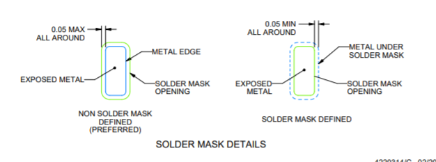
For the Solder Mask Please see below:
This is the same details we recommend on all our UQFN switches.
If you have any other questions please let me know!
We are working on adding the official drawing to the datasheet - but this may take a while as we have a few processes and multiple people to go through to add new package drawings.
If you have any other questions please let me know!