The quick answer is that the VIH (Voltage Input High) and VIL (Voltage Input Low) are the voltages recommended to be applied on the control inputs of the multiplexer for achieving a logic high and logic low. These threshold levels can be found in the datasheet.
The VOH (Voltage Output High) and VOL (Voltage Output Low) threshold levels are not applicable to analog multiplexers as these specify the output drive under some test current. TI Analog multiplexers do not drive any signal, therefore there are not VOH or VOL levels specified.
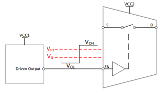
Here we will expand more on the logic levels that are applicable for the analog multiplexer; VIH and VIL. While the VOH and VOL thresholds are not driven by the multiplexer, knowing these will help determine if the device driving the logic signals will be compatible with the control pins of the multiplexer in question. The VOH voltage that is output by the driver should be above the VIH level for the multiplexer to register the input as a ‘High’ while the VOL voltage driven by the driver should remain below the VIL level for the mux’s logic pins to register the input as ‘Low’. If these conditions are not met, the switch control logic will be left unknown and will leave the switches in an indeterminable state.
Below is an illustration of the association between the VIH, VIL of the multiplexer and the VOH and VOL levels of the output driver; this will typically be processors GPIO pins.

Logic Thresholds
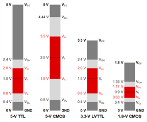
The VIH/VIL levels of your mux will not always be in line with the VOH/VOL levels of the driver. If this is the case, you may not be able to control the multiplexer accordingly. This is why it’s important to understand the logic threshold levels of the devices you are working with. Below are typical control logic threshold levels seen in most systems.

As you can see in the figure above, not all logic levels are compatible and may require a voltage translator to communicate between devices with differing thresholds. Note that Vt is the theoretical threshold level where CMOS devices will ideally switch. However, this varies in real world applications so it is not used as a threshold level for switching logic signals as you will most likely find your logic states are unstable if you do so. In TI analog multiplexer there is a small amount of hysteresis incorporated that will help alleviate these instabilities when switching with slow control input voltages where the signal may linger around this intermediate area between VIH and VIL. This hysteresis allows the device to switch from high to low or low to high at discrete levels without the concern for oscillation or uncertainty in the logic state. However, it is still recommended to drive the control pins above VIH or below VIL to help limit the overall current consumption of the device and account for any slight variations in the hysteresis thresholds.
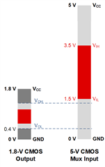
To ensure that your system can operate optimally, it is important to select a device that will be compatible with the logic levels being used in your system. Below is an example of a logic incompatibility of a 1.8V CMOS device trying to drive a mux with 5V CMOS logic inputs.

It’s easy to see here that when the device is driving a signal High or Low the 5V CMOS input at the will determine that the input is a low state and a High state will never be achieved with this configuration. These two logic devices are incompatible. You can resolve this by shifting the 1.8V output up to 5V using a level shifter or you can simply select one of TI’s many analog switches and multiplexers that support 1.8V control logic.
To check your threshold levels of a TI analog multiplexer to ensure compatibility, you’ll need to look for the VIH and VIL specification which can be found in the datasheet. Below is an example from the TMUX1574 datasheet with 1.8V logic compatible inputs. Notice here that the logic levels are not dependent on the VCC supply voltage but rather the logic levels are fixed regardless of the supply. That’s to say a device such as the TMUX1574 may be powered via a 5.5V rail and the logic inputs may reach up to 5.5V and it can still be 1.8V logic compatible.
Looking at the datasheet, we can see that as long as the device driving the logic output signals can drive a signal between 1.2V and 5.5V for the logic high and below 0.45V as low as 0V for the low, then the TMUX1574 will be logic compatible.
![]()
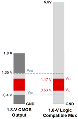
To further illustrate the compatibility of a 1.8V logic multiplexers the figure below shows an example of a logic comparison of a 1.8V CMOS device driving a mux with 1.8V logic compatible inputs. Unlike the previous figure of a 1.8V logic output driving a 5V CMOS input, where the VOH and VOL were both encompassed in the VIL region, you’ll see in this figure that the VOL is below the VIL and the VOH is above the VIH, making these two logic devices perfectly compatible.

For more information on logic input/output control levels please see the TI Precision Labs video Output/input logic levels (VOH, VOL, VIH, VIL).

