This thread has been locked.
If you have a related question, please click the "Ask a related question" button in the top right corner. The newly created question will be automatically linked to this question.
Hi,
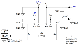
TMUX7462F protects from overvoltage beyond the VFP+VT
I need to protect a 5V level signal with GND-0.3V to 5V+0.3V (absolute max) range.
If I connect VPF pin to 5V supply, max voltage on the signal can go up to 5.7V before cut off.
Do I need additional 4.6V supply (or divider+buffer) to supply VFP?
Or can I do this with a simple series 0.4V~0.5V forward voltage drop diode on the 5V supply line? And maybe one more series diode needed for the VFN pin also to protect GND-0.3V?
(TMUX7462F will be supplied by 12V signle supply.)
And a second question when will be available this device in the stocks?
Regards,
Mete
Hi Mete,
What is the voltage range for the signal that you are switching? The VT value is listed as a typical and can vary so it is best practice to set the VFP level to as close to the maximum signal voltage range as possible. Either method (divider+buffer or diode) to reduce the voltage should work.
You can subscribe on ti.com to be alerted when the product is in stock again.
Thanks
Tyler
Hi,
I want to protect the 5V DAC outputs that connected to a connector pin.
And full range is used (0V to 5V)
If the VFP is around 4.5V and VFN is around 0.5V then TMUX7462F should protect the signal in the -0.2V to 5.2V range if I understand correctly.
VFP and VFN current specified 10uA typically in the datasheet.
I have tried to calculate a diode(MA4X194) voltage drop and compared the VT/temp graph.
According to this calculation if the VFP current is 10uA then 0.3V over-rail protection possible up to 70C.
If VFP current would be 100uA then it will protect up to 120C.
Maybe a better VF fitting diode should be selected or divider+buffer method should be used.
What do you think about this method? What do you recommend?
Thanks, Regards,
Mete
Hi Mete,
Your understanding is correct, with VFP at 4.5V and VFN at 0.5V then the clamping voltage should be around 5.2V and -0.2V based on the typical VT value.
If the application calls for temperatures over 70C, then a diode with a lower drift over temperature would be recommended. Or, as you mentioned, a buffer+divider may also be the better option over temperature since you can select resistors with very tight tolerances and a buffer with a wide temperature range.
In general, I would recommend evaluating either option on a board because it sounds like this application calls for tight clamping specs. TI offers an EVM kit for this device to help with this.
Thanks,
Tyler