Hello,
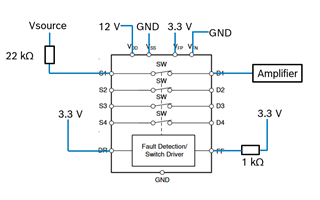
I integrated the TMUX7462F as protection from voltages above 4V according to the following draft into my system:

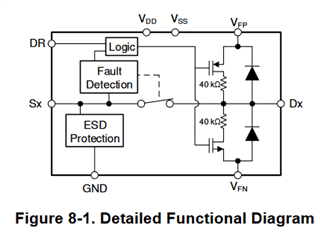
According to the datasheet, my expectation was that the switch SW should open, once Vsource exceeds 4V (3.3 V at VFP + 0.7 Vth). However, I noticed, that I need to apply more than 14 V at Vsource before the SW opens. At voltages between 4 and 14V, S1 is clipped to roughly 4V. In this region, a significant current is flowing through the 22 kOhm resistor into S1. This current reaches approx. 470 µA before the overvoltage detection triggers, which is way above any leakage current stated in the datasheet at room temperature. After revising the datasheet again, I noticed the internal diode between D1 and VFP, which might sink current into VFP until it's breakthrough is reached (obviously around 470 µA). Then, any voltage increase at Vsource also increases the voltage at S1, thus triggering the overvoltage status. 
Can you confirm, that this behaviour is correct and I don't have a damaged chip? Further, is there any section in the datasheet that I missed or is my assumption correct, that the diode is causing this "issue"?
For my application, I need the voltage at S1 (below the 22 kOhm resistor) to be as high as the Vsource. Is there any possibility to do this with this setup?
Thanks for your support!
Best regards,
David

