This thread has been locked.

If you have a related question, please click the "Ask a related question" button in the top right corner. The newly created question will be automatically linked to this question.

CD74HC4067: A SPI's CLK signal (20MHz) is distorted after passing CD74HC4067 MUX

Part Number: CD74HC4067
Other Parts Discussed in Thread: TMUX1574, SN74CB3Q3251

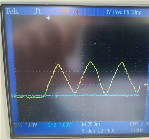
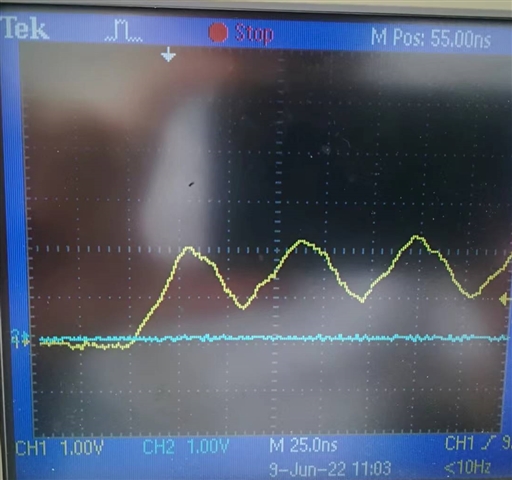
There are ASIC chips with SPI master. We choose one specific ASIC chip with CD74HC4067 MUX. The CLK signal is OK at the master side; however, the signal is distorted after passing CD74HC4067 MUX. Since the CLK signal is not OK, the SPI communication cannot work properly. We wonder how to fix the problem. Thanks.

The connection is as following:

SPI's CLK (Master)  ----> CD74HC4067 MUX ----> FT2232HQ (USB Hi-Speed to Dual Channel Serial UART/FIFO/JTAG/SPI/I2C IC)

The CLK signal at Master side:
The CLK signal passed the CD74HC4067 MUX
  • Hi,

    When the signal was measured on the output of the mux, was the FT2232HQ connected to that line and are there any other components(capacitors/resistors) connected? Can you remove the mux and directly connect the signal to the FT2232HQ to see if the distortion is still present?

    What is load impedance that the mux is feeding into? The RON from the mux can cause attenuation but the amount depends on the loading conditions.

    Thanks,
    Tyler

  • Thanks for your reply, Tyler.

    The FT4222HQ-D-T (It is FT4222, not FT2232HQ.) is connected to the output (COMMON, PIN1) of the MUX when the signal was measured on the output of the MUX.

    When we remove the MUX, connecting directly to FT4222HQ, there is no CLK signal distortion. The circuit behavior  is what we expected. But here, we need the MUX for our application.

    Actually, the output of the MUX is feeded into FT4222HQ; but we do not know how to determine the load impedance. If the load impedance matters, then how do we match the load impedance?

    Thanks.

    Youbao

    The datasheet of FT4222HQ-D-T is attached to this message for convenience.

    DS_FT4222H.pdf

  • Hi Youbao,

    Since this is SPI and doesn't require pulldown resistors, the on capacitance of the CD74HC4067 could be the issue. It has 50pF input capacitance which likely isn't letting the signal swing the full voltage range. Is the clock signal for your application normally a triangle wave? We test/spec our devices with a square wave.

    Is it possible for you to share the schematic so we can give a more accurate help?

    Thanks,
    Tyler

  • The schematic is as following. The MUX can be changed to other types of MUX. For the FT4222HQ part, the most relevant schematic is shown.

    Actually, we've tried several MUXes:

    ADG725BSUZ (16:1)
    CD74HC4067 (16:1)
    ADG706BRUZ (16:1)

    They all cannot satisfy our application. The 20MHz CLK signal is somehow distorted, so the SPI communication cannot work properly.

    Finally, The MUX of TMUX1574 (4 channels of 2:1 SPDT) does the job.

    We guess here the relevant parameters of the MUX are on-capacitance, on-resistance, and bandwidth.

    Since the 16:1 MUX is the most suitable IC for our application, could you please recommend a 16:1 MUX which parameters are similar to TMUX1574?

    20220620SPI_MUX_CLK_20MHz.pdf

  • Hi Youbau,

    16:1 devices are usually harder to get better switching performance out of due to the fact there are 16 switches connected to one output (basically, 16 capacitors so the switching speeds are directly impacted by that increased capacitance). I would recommend trying to use 2x of the SN74CB3Q3251 which has a rated bandwidth of 500MHz (just tie the outputs of the devices together to form a 16:1 device) and should exhibit higher switching performance.

    Let me know what you think.

    Thanks!

    Bryan

  • Thank you for your help, Bryan.

    In our application, the switching speed is not so important. Once the switch is on, we are most caring about the parameters of on-capacitance, on-resistance, and bandwidth.

    If we could tie the outputs together, then we may have two choices for our application.

    1) we could use 8X TMUX1574 to select one group of 16 groups of SPI signals, provide that we tie the corresponding 8X D* together and properly controlling the EN signals;

    OR,

    2) we could use 2X SN74CB3Q3251 to select one signal of SPI signals, and then we use 4 groups (i.e. 4X (2X SN74CB3Q3251)) for our application.

    For the above two approaches, which one do you think better?

    Thanks.

    Youbao

  • Hi Youbao,

    The one thing that may be of concern is that if you use the TMUX1574, you will not be able to select just one input at a time as each switch is not individually controlled like the SN74CB3Q3251. You will always have at least 4 inputs connected to the output as there is only a single SEL pin to switch the channels. I would advise using the SN74CB3Q3251 for better control of which channel you would like to have on.

    Thanks!

    Bryan

  • Thank you Bryan.

    Best regards,

    Youbao