This thread has been locked.

If you have a related question, please click the "Ask a related question" button in the top right corner. The newly created question will be automatically linked to this question.

Boot Mode pin selector

Other Parts Discussed in Thread: SN74LVC2G66, TMUX1574, TS5A23157, TMUX1309, TS5A3357, TS5A3359, SN74LV4066A, SN74CBTLV3257

Dear members, 

We need to be able to have three different ways for burning the firmware into the micro. 
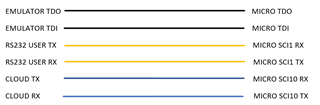
1- Emulator

2- RS232 driver User MODBUS

3- RS232 driver from our cloud

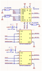
each of these ways has its own assigned pins in micro. I want to find a kind of chip that let me choose (or switch) between different pins while burning the firmware. In RUN MODE the connections are like:

RUN MODE MD=1

BOOT MODE MD=0 using USER MODBUS

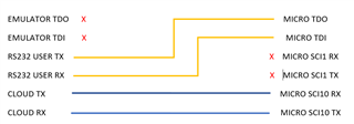
BOOT MODE MD=0 using USER CLOUD

any suggestion would be appreciated. 

Farzaneh

  • When looking at the left side, the EMULATOR TDx signals just need to be disconnected; use 1:1 switches like the SN74LVC2G66.

    For the RS232 USER and CLOUD signals, use 2:1 switches like the TS5A23157 or TMUX1574.


    Alternatively, when looking at the right side, for the MICRO TDx signals, you can use 3:1 multiplexers like the TS5A3357 or TS5A3359. But a two-channel 4:1 device like the TMUX1309 is cheaper.

    The MICRO SCIxx signals just need to be disconnected; use 1:1 switches like the SN74LVC2G66 or SN74LV4066A.


    Better recommendations might be possible if we know the voltages and frequencies.

  • Hey Farzaneh,

    I think Clemens solutions are good! I took a look before seeing his solution and came up with same feedback as his second "Alternatively" plan. TMUX1309 would be a good cheap option and really any 1:1 switch for connnecting and disconnecting the SCI signals. 
    But also has he mentioned, voltage and frequency would help determine whether the solutions are viable here.

    Thanks,
    Rami

  • Dear Clemens,

    The signals will be connected to a micro with frequency of 12MHz and 3V3. I will take a look at what you have already suggested.

    Thanks a lot

    Farzaneh

  • I chose the switches mentioned above for 5 V support. They work well at 3.3 V, but you can also consider the SN74CBTLV3257 as a 4-channel 2:1 switch.

  • Hello,

    There is sth else that I need to know. Is it possible to connect serial ports (SCI signals) to Jtag ones(TDI/TDO)? They are using different protocols and I guess I can't connect them directly. Maybe I need a convertor in between. 

    Farzaneh

  • A switch cannot help you with this.

    "SCI" is not a protocol, and I do not know which JTAG protocol you're using. A converter would be a microcontroller, but I guess you already have a microcontroller in your system. It might be possible manage the JTAG protocol with GPIOs.

  • Dear Clemens,

    I could find out that TDO/TDI ports of the microcontroller also support de SCI signals. It has been mentioned in MICRO datasheet. Now I need only to put the MUX for connecting the lines and also disconnecting them. 

    Thanks a lot

    Farzaneh

  • Dear Clemens,

    Just the last question to confirm that everything is correct.

    I made this circuit:

    where I used the analogue switches, I need them to open or close simultanously. I've thought I could use one ontrol signal for both. Is it OK? or do I need to consider more things?

    Thanks

    Farzaneh

  • Yes, it's possible to use the same signal for multiple CMOS inputs.

  • Thanks for all your support.