This thread has been locked.

If you have a related question, please click the "Ask a related question" button in the top right corner. The newly created question will be automatically linked to this question.

SN74LVC1G3157: switches before switch signal applied

Part Number: SN74LVC1G3157
Other Parts Discussed in Thread: TS5A3159A,

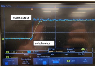
We have a board which biases SN74LVC1G3157 switches at 5.0V but the switch signal is driven by 3.3V I/O. This was a design mistake which we'll rectify, but our concern is for systems already deployed. Checking signals, we see switching occurring consistently but in some cases outputs switching just before switch signals begin to transition. We speculate noise at the start of switch signal assertion is somehow causing switches to switch prematurely? Perhaps excessive shoot through currents damaged the switches to make them susceptible to this behavior? Our new TS5A3159A switches don't do this and switch as expected. Here are example waveforms:

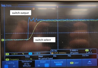
Can anyone explain this unexpected behavior?

Shel

  • The example waveform does not show any noise at the select signal, but something must affect the switch (unless you've invented a time machine). Is there ringing on the VCC or GND lines? Is there a nearby decoupling capacitor?

    The TS5A3159A has a VIH of 2.4 V, so it is guaranteed to work reliably.

  • Thanks Clemens. There is a decoupling capacitor nearby. There's about 50 mV peak to peak noise on ground. We replaced the SN74LVC1G3157 with a TS5A3159A at the same position and it works as expected:

    The only thing I can think of is the SN74LVC1G3157 threshold is somehow close to ground. The funny thing is we see this same behavior in multiple SN74LVC1G3157 parts. One concern I have is that for shipped units the parts may someday switch on at other times when they're not supposed to.

    Shel

  • I guess that "BW" symbol indicates a bandwidth limit? Please disable it.

  • The BW filter is turned off. You can see a fast rise time of less than a few nS on the switched output waveform.

  • I'm talking about channel 1.

  • The same time base applies to both channels. Channel 1 switch select is somewhat slow with a rise time of about 20 ns but that's still within recommended operating conditions.

  • Why does the oscilloscope show "BW" on channel 1?

  • Hey Shel,

    It wouldn't make sense for the switch to switch before the control signal comes in. There's no way it would know this change was coming. The BW symbol could be affecting the actual readings here. If you aren't sure how to disable this and remove the symbol or can't find the users manual could you maybe switch the channels and see how that looks or use a different channel entirely where BW isn't active?

    There doesn't look to be any noise on the control pin so i'm doubtful that some noise is triggering this. If you still feel it's noise related though, take a quick probe of the GND and VDD and confirm that they are stable.

    Thanks,
    Rami

  • Thanks Clemens and Rami. I wasn't the one who captured these waveforms and unfortunately don't have access to that system. Good catch Clemens, I see bandwidth limiting was enabled on the select channel. That explains the slower select rise time but I don't think bandwidth limiting could delay the start of the select signal transition nor would it explain why the SN74LVC1G3157 switched earlier than TS5A3159A under the same settings even though the SN74LVC1G3157 is supposed to have higher switching threshold. There is some ground noise of about 50-100 mV p-p.

  • Hey Shel,

    It still doesn't make sense here that the signal to be switched before the trigger. Damage to the device can certainly skew the effective logic levels but I'm not sure how this behavior would exist. Something would have to trigger the even of switching. The device has no way of knowing that a trigger is about to occur. 

    With what we know now, I feel that this is a measuring error. We will need more waveforms and testing to be able to move forward. I would also ask for double checking that the signals are indeed what they say they are and they weren't mixed up (ie the control signal is actually our I/O and vice versa). 
    If it is at all possible to get new signals, seeing what a correct signal looks like would also be beneficial. And removing the BW limiting would also be beneficial. Both signals aren't tested with the same conditions so it's hard to tell what's happening.

    Can you also let me know what are the expected NC/NO signals here when switching? A schematic and where the probing occurs could be useful too. 

    Thanks,
    Rami

  • Thanks Rami, your comments are helpful. This is for a program for which I may not be able to get resources for further testing soon. I'll put in a request but meantime mark this as resolved since I can't think of how else you could help shorter term.

    Shel