This thread has been locked.

If you have a related question, please click the "Ask a related question" button in the top right corner. The newly created question will be automatically linked to this question.

TS5A22364-Q1: Schematic Review

Part Number: TS5A22364-Q1
Other Parts Discussed in Thread: RC4580

Hi Expert,

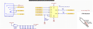
Please review the below schematic, we are using TS5A22364-Q1 as audio mux feeding two laptop audio aux signals as shown in image. Those output stereo of selected laptops from mux are going to RC4580 OPAMP.

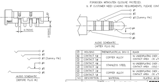
Question are I didn't get any signal on output side when I plug the aux cable into audio aux connector.  Am I doing anything wrong? Where to connect the 1st pin(GDN) of audio connector?

  • Hey Mohit,

    I'm not seeing anything that particularly stands out. Can you send some waveforms of the I/O's and the power supply? 

    I'd recommend to tie your pin1 GND (GND_LP1) to the system ground. So the same ground that the 22364 device is using as ground. 
    I think technically your pin 3 should be your tip (audio left) and pin 4 that you're using is used as a bias for pin 5 which would be a detection pin but electrically speaking, the way you're doing it should be fine since you're shorting pins 4 and 5 together. It probably isn't a problem but figured it wouldn't hurt to bring up too. 

    Thanks,
    Rami

  • Hi Rami,

    The pinout of aux jack as shown in the image. Pin no. 3 won't be the issue for this circuit. 

    Though, I give pin1 of aux connector to common GND of system.

    Please check some waveform of audio signal on scope: Input left of aux connector 

    Input Right of aux connector 

    Output of TS5A22364-Q1 Left audio 

    Output of TS5A22364-Q1 Right audio 

    Thanks,

    Mohit

  • Mohit,

    This looks like noise on both ends and some noise filtered out at the output. Are you actually applying an audio signal on the input? Or is this just extremely zoomed out relative to the scope of the audio signal levels?

    Can you bypass the mux and see if there is audio there to start?  

    Can you probe the supply and the control pin as well with the input/outputs. Having them on the same graph vs multiple individual waveforms would be preferred here too.

    Thanks,
    Rami

  • Rami,

    Yes, I have applied actual audio signal( music). I don't know much about laptop aux audio waveform. Could send some waveform or frequency, Vrms relevant stuff for audio signal?

    I will probably send you multiple waveform tht you required tomorrow.

    Input waveforms are directly measure from audio aux 3.5mm plug pins.

    Thanks

    Mohit

  • Hey Mohit, 

    I'm not expert on audio waveforms as well (we do have an audio E2E for more audio specific questions : https://e2e.ti.com/support/audio-group/audio/f/audio-forum) but my point here was to confirm that we're actually providing a signal to the input of the mux.
    Instead of using actually audio, I'd recommend applying a 1kHZ tone wave just so we can see whether we're switching properly or not. Focus on making sure that we can switch the signals first. This is what I'm looking for in the waveforms. Ideally, we can see a 1kHZ inputs, the state of the control pin, the supply pin voltage and the common output and see what's going on there.

    Another option here would be to also ABA swap the device. So replace the current 22364 with a new one and see if the problem follows the specific device.

    Thanks,
    Rami