This thread has been locked.

If you have a related question, please click the "Ask a related question" button in the top right corner. The newly created question will be automatically linked to this question.

TS3A5018: TS3A5018RGVR IBIS model questions

Part Number: TS3A5018

Hi there,

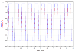
We use TS3A5018RGVR to switch SPI signal on our board and find signal reflection on  clk. 

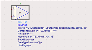
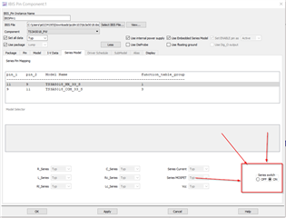
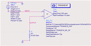
So we downloaded simulation model from ti.com to simulate signal. But we have some question about the IBIS model.

1. how to set the drive source of signal, from our Controller or from this analog switch?

2. If the drive source should be our controller, why not provide S parameter model, but IBIS model.

3. If the drive source should be the analog switch, how do we set drive strength of signal. And if the drive strength of analog switch have any relationship with drive strength of our controller.

BRs

Shubiao

  • Hey Shubiao,

    The drive source should be the controller. The switch doesn't drive any source, it is simply a passive switch. We created an IBIS model so that it can be used in IBIS software. If I had to guess, it's a pretty low bandwidth device so when the device was created, s-parameters weren't taken into consideration. IBIS, however, is standard for all our devices. 

    Thanks,
    Rami

  • Hi Rami,

    Could you provide user guide and test bench of the ibis model ?
    Or let me know how to connect the for port?

    BRs,

    Shubiao

  • Hey Shubiao,

    I don't have a guide on hand, but i'll try and walk you through how to set this up!
    So you'll actually want to run this as a "IBIS_PIN" model. I'm using Advances design system (ADS) so the model terminology may be slightly different if you're using a different software. But here's the example : 


    Double click on the model and a popup with some configuration options should appear. Here, you'll first want to select your ibis file you'll be using at the top: 


    From there, after you've added the model, you'll be able to select the pin you'll be using and the supply voltage. You'll want to pick one of the I/O's (NC,NO,COM pins) and you will be given two options in the model selector below. This is where you'll select the correct supply voltage for the path you'll be modeling.


    The model should now look like this where where the input is one pin and the output is the second :

    You should now be able to use the model as a simple passive path.
    Note that with each model you can only model a single signal path. So if you want to model multiple paths, you'll need to put multiple models down.
    Additionally, if you want to connect and disconnect the switch (turn it off/on) this can also be found in the Series model tab if you double click on the model:

    I did a quick example with the model here with some pulsed input and a load : 

    And the results : 


    Let me know if this helps or if you have any other questions!

    Thanks,
    Rami