This thread has been locked.

If you have a related question, please click the "Ask a related question" button in the top right corner. The newly created question will be automatically linked to this question.

MUX36S08EVM-PDK: Parameters and attenuation issues.

Part Number: MUX36S08EVM-PDK
Other Parts Discussed in Thread: MUX36S08, MUX508, TMUX1308-Q1, SN74CBTLV3253, SN74CBTLV3251, TMUX1309-Q1

Hi all, 

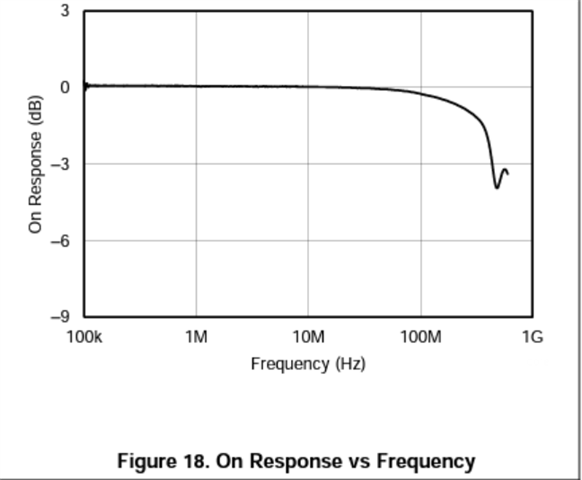
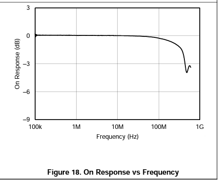
1. The bandwidth on the MUX36S08 datasheet shows 500MHZ, Not sure what this figure means about, on datasheet page 13,figure 18.
2. I have several Sine wave signals that need to be switched and measure.

  • DC : 1.2V 
  • AC :  amp 400mV 
  • Frequency : 100MHZ 

I was using the TINA MUX508 model for modeling as TI suggest. 

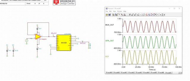
I found that the output results(MUX_OUT) are attenuated, why is there such a attenuated, how to calculate, where will this parameter be displayed in the datasheet? 

 VG1 on TINA : DC Level : 1V / Sinewave, 400mV, 100MEG.
Thanks,

Frank

  • Hi Frank,

    Welcome to the forum!

    1. The bandwidth on the MUX36S08 datasheet shows 500MHZ, Not sure what this figure means about, on datasheet page 13,figure 18.

    This is figure is showing that this device is rated at 500MHz due to having -3dB attenuation at this frequency. 

    2. I have several Sine wave signals that need to be switched and measure.

    • DC : 1.2V 
    • AC :  amp 400mV 
    • Frequency : 100MHZ 

    I was using the TINA MUX508 model for modeling as TI suggest. 

    I found that the output results(MUX_OUT) are attenuated, why is there such a attenuated, how to calculate, where will this parameter be displayed in the datasheet? 

     VG1 on TINA : DC Level : 1V / Sinewave, 400mV, 100MEG.

     So, from what I can see here is that the MUX_OUT follows OPA_OUT closely with a ~70mV loss. This loss is due to the RC filter effects of the analog switch so if we can reduce the on resistance then that can help with our attenuation issue. The frequency diagram from above is simulated based on a 50Ohm load. It looks like a 1MOhm load is being used in your model although this is likely just the scope. 

    Is there a reason you are using one of our 36V, 8:1 parts when you are sending signals <2V and only one input to one output? I assume the one input one output is for simulation purposes only. Is the very low on capacitance a key care about here? We have plenty of lower cost, low voltage parts (with automotive qualification if needed) that I can recommend such as the TMUX1308-Q1 or TMUX1309-Q1 (also available in non-auto qualified versions). These 8:1 parts offer a cheaper solution with lower on resistance to lessen the attenuation you're seeing. Also of note are the SN74CBTLV3251 or SN74CBTLV3253 devices. 

     I'd love to know more about the use case here in order to provide a comprehensive solution. 

    I am looking forward to hearing back from you!

    Alex 

  • Hi Alex, 

    1. I'm not sure if you have answered this question already, can you please explain what does this figure mean to signals? 


     So, from what I can see here is that the MUX_OUT follows OPA_OUT closely with a ~70mV loss. This loss is due to the RC filter effects of the analog switch so if we can reduce the on resistance then that can help with our attenuation issue. The frequency diagram from above is simulated based on a 50Ohm load. It looks like a 1MOhm load is being used in your model although this is likely just the scope. 

    As you reply, RC filter of analog switch cause the loss, Is there any way that I can approximate calculation the loss? R = Ron(typ) , C = Con(typ)? 

    Is there a reason you are using one of our 36V, 8:1 parts when you are sending signals <2V and only one input to one output?

    Just coz this EVM board is on hand and also fit the requirement for this test.  

    Thanks for the recommend!

    Br.

    Frank

  • Hi Frank,

    1. The figure represents the -3dB point for this device: 500MHz.  It is the frequency at which the output power of a system is half of its input power. For example, since this device has a -3dB point 500MHz, it means that the device will start to significantly attenuate frequencies above 500MHz.

    As you reply, RC filter of analog switch cause the loss, Is there any way that I can approximate calculation the loss? R = Ron(typ) , C = Con(typ)? 

    So there's not a direct way to calculate the loss here just from Ron and Con. I believe you're seeing more attenuation in the model than you would see in real life - perhaps due to loading conditions. We may be able to perform a quick test in the coming days here in the lab to simulate how much signal attenuation actually exists. Another option is to grab a device with higher bandwidth so that there's near 0 attenuation at 100MHZ - if you refer to the On response vs Frequency plot you can see some attenuation exists at 100MHZ. 

    Thanks!

    Alex