Other Parts Discussed in Thread: MUX36S08, MUX508, TMUX1308-Q1, SN74CBTLV3253, SN74CBTLV3251, TMUX1309-Q1
Hi all,
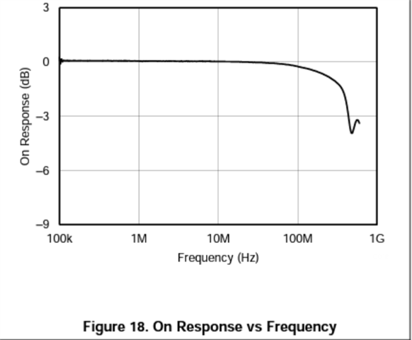
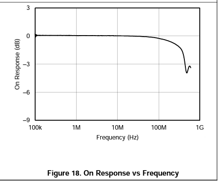
1. The bandwidth on the MUX36S08 datasheet shows 500MHZ, Not sure what this figure means about, on datasheet page 13,figure 18.
2. I have several Sine wave signals that need to be switched and measure.
- DC : 1.2V
- AC : amp 400mV
- Frequency : 100MHZ
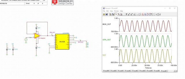
I was using the TINA MUX508 model for modeling as TI suggest.
I found that the output results(MUX_OUT) are attenuated, why is there such a attenuated, how to calculate, where will this parameter be displayed in the datasheet?
VG1 on TINA : DC Level : 1V / Sinewave, 400mV, 100MEG.
Thanks,
Frank