This thread has been locked.
If you have a related question, please click the "Ask a related question" button in the top right corner. The newly created question will be automatically linked to this question.
e2e,
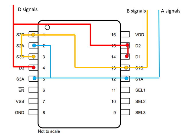
Can TMUX4053 support 30mA if we were to parallel all three terminals, effectively using the triple SPDT as a single SPDT? I think the layout is working against us in this particular use case, but it may still be a worthwhile option. (I hacked something together, but I’m sure it could be improved.)
Thank you,
Adam
Yes; the absolute maximum ratings allow this.
I suspect that a high current also implies that you want a small voltage drop over the switch. So consider a low-Ron switch like the TMUX6219.
Hey Adam,
Clemens is correct here. No problem in doing this since you'll be limiting the current through each individual switch. That being said, also as Clemens mentioned you can acheive this with a single switch.
Depending on the voltage range needed needed or any other spec interest or price interest there are a few options.
If working with low =<5V SN74LVC1G3157 is a good cheap option.
For higher voltages, which I assume you are using given the TMUX4053 decision, I would stick with Clemens suggestion of the TMUX6219.
You can also realize the results with a slightly cheaper solution in the TMUX6123 and tying S1 and S2 together and tying the SEL1 and SEL2 together. This would be a higher RON solution though.
Thanks!
Rami
Clemens, Rami - Adam posted this on my behalf. Thanks for confirming. I am looking for a low cost (< $0.30) 2ch SPDT switch that could support 13.8V and up to 25mA on each channel. TMUX4053 x2 hits the electrical and price targets, I think. Would you agree or would you suggest something else?
Hey Brian,
Yes, for that price point, this looks to be the best option. I can help a little with the optimization here though on the traces. I worry about running the trace from S1B to S3B that you have going between two pins. The clearance will be a little tight and I can see there being some opposition to actually designing it this way. I think the layout below may be a little better. It also would allow for some semblance of flow-through routing with the two A and B signals on out side and the common D signal on the other side of the switch.
Thanks,
Rami