This thread has been locked.

If you have a related question, please click the "Ask a related question" button in the top right corner. The newly created question will be automatically linked to this question.

SN3257-Q1: IBIS Model for SN3257 not functional

Part Number: SN3257-Q1

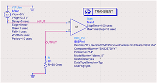
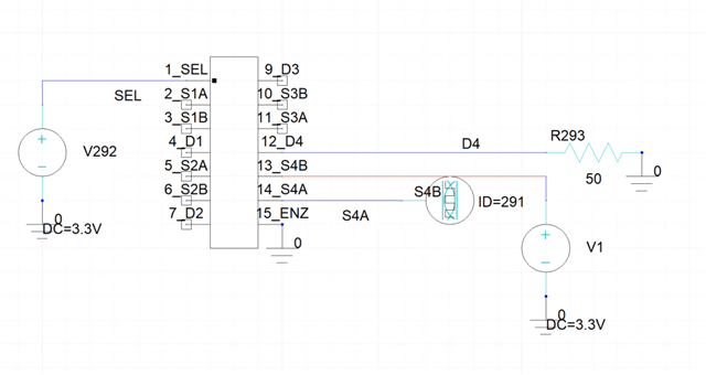
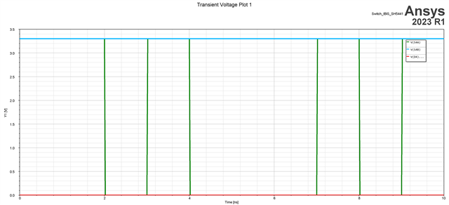
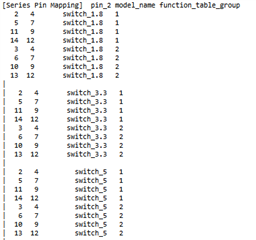
I've doownloaded ibis model from your website for this analog switch, but it doesn't work after I imported it into the sim tool. No matter how I tune the SEL/EN, and add some voltage levels at the pin a1 and b1, but nothing comes from d1. 

Please help to check what goes wrong. 

Thanks.

  • This is a passive switch; it does not have buffered I/Os.

    I do not know what simulation tool you are using. But the IBIS model contains only information about the on-resistance of the switch, i.e., the voltage/current relationships between the S1A/S1B and D1 pins.

  • We are using Ansys. It is basically on res and cap that matters of course, but what we want to build is to get the switch in our signal channel, and transmit a signal through the switch and observe the signal at the receiver. But no matter how I set, nothing could pass through this switch model. 

  • Hey Li,

    We usually test things out in Advance Design Systems (ADS) and/or Hyperlynx. I'm not very familiar with Ansys so I'm not sure how much support I can provide and you may have some look reaching out to Ansys support or if you want, you can share some of the process you've been going through to try and get this to work and I can try and help in anyway I can. But note, as I said, I don't have much experience with Ansys so I may be no more than help other than an extra pair of eyes and hands to look things up with you.

    That being said, I did do a very quick and barebone simulation on the model in ADS to ensure that it does function and I did get a signal to go through as you're looking for. 

    So I don't believe it's an issue with the code but something with how it needs to be setup within Ansys itself.

    Thanks,
    Rami

  • Hi Rami,

    Thanks for the reply. Yes, different tool might handle the model differently. Here I try to post some snipped pictures of ansys import:

    This is if I import as component

    Then I can set the pins into different terminator options, for example here:

    Then I set the circuit as this

    And I got the result as below. The signals doesn't pass through, so D4 kept low.

    Could you see anything that suspecious? I will try to reach out to Ansys as well, but there aren't much that I could set here in the tool for the switch. 

    BR

    Li

  • Hey Li,

    I can't really see anything that stands out as an obvious solution. 
    My only thoughts that I can add here are that typically I select two pins for the signal path while here it looks like you can only select 1.
    Additionally, did you change the code to comment out the 1.8V rail and uncomment out the 3.3V rail? The default state is 1.8V. The '|' to the left of the line indicates commenting out


    Thanks,
    Rami