Hi Sir,
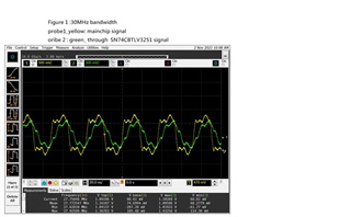
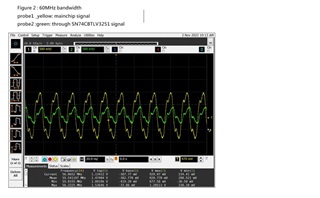
after the signal is output from main chip and pass through SN74CBTLV3251, the square qave will be distortion at 60Mhz,
we would to know what could be the problem here?


This thread has been locked.
If you have a related question, please click the "Ask a related question" button in the top right corner. The newly created question will be automatically linked to this question.
Hi Sir,
after the signal is output from main chip and pass through SN74CBTLV3251, the square qave will be distortion at 60Mhz,
we would to know what could be the problem here?


The SN74CBTLV3251 has a specified bandwidth of 200 MHz. The attenuation in figure 2 happens already at 60 MHz, so I guess there are additional resistances and capacitances in the circuit. Are there any long traces, cables, or connectors? Please show the schematic and the board.
HI Clemens Ladisch
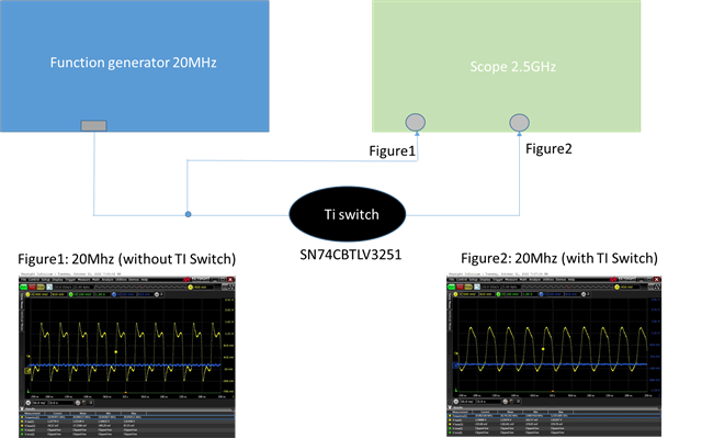
Here is my block diagram.We still confuse why the signal pass the switch will distortion at 60 MHz??

Hey Calvin,
I'm merging from this thread : https://e2e.ti.com/support/switches-multiplexers-group/switches-multiplexers/f/switches-multiplexers-forum/1287379/sn74cbtlv3251-signal-pass-the-switch-ic-will-be-distortion
Nothing here really stands out as the root cause but can you clarify on your waveforms what each wave represents.
Is yellow bypassing the mux and green through the mux? it looks like your signal integrity drops at 60MHz even without the mux while the 60MHz signal through the mux does have more of a drop probably due to the extra capacitance. What's the DUT and what's the capacitance there? I see your probes are 9.5pF.
Additionally what do the board traces look like? Are they particularly long or thick?
Do you have another source you can use for debugging here besides the DUT?
Thanks,
Rami
Those cables (and their connectors) can have quite a high capacitance and inductance.
If you want to measure the high-frequency characteristics of your intended solution, then you have to create a real PCB.
1.
Figure 1: 30MHz
Yellow (Probe1):Controller output
Green (Probe2): Output after SN74CBTLV3251PWR
Figure 2: 60MHz
Yellow (Probe1):Controller output
Green (Probe2): Output after SN74CBTLV3251PWR
2.
DUT (device under test) is the output terminal of the IC controller.
3.
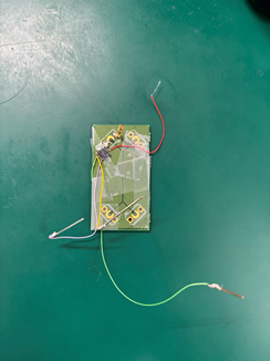
The switch IC sample look like the figure below

4.
We have also tried to use the Function generator to directly pass the output signal.
The measurement results are as shown below :

Hello Jeff,
For such high frequencies application, using DuPont wires is not recommended since they have high parasitic capacitance that will cause distortions in the signal.
Could you please provide a picture of your setup with everything connected?
Your issue could be related to parasitic distortions or noise.
Thanks,
Nir