A related question is a question created from another question. When the related question is created, it will be automatically linked to the original question.
If you have a related question, please click the "Ask a related question" button in the top right corner. The newly created question will be automatically linked to this question.
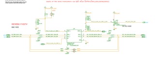
It is I3C level translation with this device from 1.2V to 1.8V. SCL1/SCA1 level are 1.2V, but SCL2/SCA2 level are not 1.8V.Any comments about this issue?
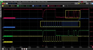
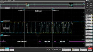
If you look at the signals that you boxed off, the signal is attempting to rise to 1.8V but is quickly cutoff being driven low by the i2c driver controlling the bus. This means that the rise-time is too large and needs to be reduced.
Clemens has suggested changing the pull-up resistors to be stronger i.e. lower value. The pull-ups that you have in your system, try reducing the pull-ups to half their value.
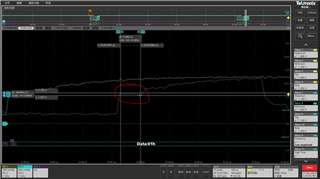
100 ohms is very strong pull-up. Are you suggesting you were using 200 ohm resistor before? Is there a reason you chose 100 ohms? Choosing this strong of a resistor increases the VOL as you have seen in the scope. The voltage level is very high. IxC operates of VIH and VIL voltage levels.
VIH = 70% of VCC
VIL = 30% of VCC
The input low-level requirement for VCC = 1.8V is VIL = 0.54V
The input low-level requirement for VCC = 1.2V is VIL = 0.36V
The 650mV VOL is too high for the low level input voltage for 1.8 V and 1.2V logic. This means that the pull-up resistor is too strong. Do you have other options to increase the resistance? If increasing the resistance causes the signal to not rise to a VCC in time before switching back to logic low, this means there is too much capacitance on the I2C bus either from parasitic PCB trace cap, input cap, long cable lengths, etc. There may need to be a reduction in parasitic which could mean shortening the traces for using less wire in system application.
The SCL looks to be oscillating ~1MHz if looked at from a us/div perspective. 10us/div is the scope. Measurement 6 says 8.201MHz, but this seems inaccurate. Is the TCA39306 being used for I2C or I3C related application?
In I3C, parasitic bus capacitance is key here. I3C requires that bus cap < 50pF. This includes parasitic bus cap present on the combination of side 1 and side 2 of the TCA39306 due to the passivity of the device. I.e. TCA39306 is a passive level translator, it does not re-drive the IxC bus, therefore, 50pF on side 1 and 50pF on side would equate to a total parasitic bus cap of 100pF which is outside the I3C spec.
Parasitic bus cap can come from PCB trace length (1pF/cm or 3pF/inch for estimation), input cap (each slave/master device provides about 10pF input cap per device). There is not much room for excess parasitic capacitance and should be taken seriously in design. It looks like the system is struggling to find a balance between to large VOL and too slow of rise-time.
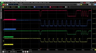
In the waveform where top=1.66V, rise-time is slightly too long. It needs to be faster which means that either Rpull-up needs to be stronger, or excess parasitic bus cap needs to be accounted for and reduced.
Please see this application note describing how to calculate the appropriate pull-up resistance for an I2C system. This app note has similar implications for I3C.
In scope 2, the non-monotonic signal comes from a combination of inductance on the wire, fast data rates, and the fact that parasitic bus capacitance exists on both sides of the level translator which in effect causes a slight dip upon rising edge. I believe the way to mitigate this is to introduce series resistance in order to filter out high-frequency noise, but this is not feasible for I3C since clock is 12.5MHz. Another way to combat this is to reduce trace length or any other inductive paths.
TCA39306 does not re-drive IxC signal. It is a passive level-translator.
A device like the TCA9617B does re-drive the signal by buffering the two I2C busses.
Also, a quick test to conduct to see if the system is failing due to rise-time is to slow down the data rate via software. See if this fixes the issue temporarily. If slowing down the data does fix the issue, then we know if the main problem is due to selecting the correct pull-up resistance and dealing with excess parasitic bus cap.
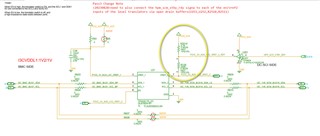
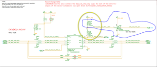
The current customer design is somewhat different from the datasheet implementation. We don't recommend a 4.7kohm series current limiting resistor, nor do we provide an option to quickly switch between 1.8V and 3.3V translation.
What I am trying to get as is is that R2510 is going to have some current flowing through this resistor (it will be small). When there is a current and resistance, there is a voltage drop. So seeing that 1.75V at VREF2, I am not surprised due to the voltage drops that would accrue across each series resistor. 0.05V would seem reasonable due to this idea.
Also how accurate are the 1.2V and 1.8V supplies from the customer? Has the customer measured the actual voltage of the power supplies? How accurate are they to the nominal voltage listed in the schematic? I.e. 1.8V supply could be 1.79V, small voltage drop across 4.7k and 200k, could lead to 1.75V at VREF2.
There also might be some leakage from the 3.3V buffer side as well. I would expect this to be a very small current, but a current nonetheless.
TCA39416 is basically the same device as TCA39306 but with active circuitry such as the rise-time and fall-time accelerators that would help with driving the rising and falling edges in IxC.
The 20'' wire equates to roughly 60pF of parasitic cap. 20'' x 3pF / inch = 60pF. 3pF / inch is a good estimate when routing traces on a PCB this result could vary depending on the trace width, layer height, etc. This also doesn't account for the input cap provided by the TCA39416 and whatever cap is present on the I3C_Hub connection. I3C only allows for 50pF of cap on the bus lines. Anything above this and the bus is technically out of spec. In an I2C application, we would recommend a buffer in this scenario, but due to I3C being relatively new in the market, not many I3C capable buffers exist. TCA39416 in this case would help here, but this device is not a true buffer (the combined parasitic cap of the 1.2V side and the 1.8V side will appear in parallel). The I3C bus may be out of spec, but the RTA/FTA combination would help with driving the transitions of I3C.
What I am trying to say here is that the current block diagram is most likely out of spec for I3C due to 50pF cap limit, but the TCA39416 might be successful in allowing this over-cap due to its ability to drive edge transitions with assistance from RTA/FTA combo.
In the past, TCA39416 has been tested with total cap of ~100pF at 12.5MHz in our lab. The signal results were OK. I would expect an I3C capable receiver to correctly ACK even with the added over-spec cap utilizing the TCA39416.