This thread has been locked.

If you have a related question, please click the "Ask a related question" button in the top right corner. The newly created question will be automatically linked to this question.

MUX36S16: Leakage current and integration for multiplexed impedance spectroscopy applications for high-impedance test devices

Part Number: MUX36S16
Other Parts Discussed in Thread: TMUX1108

Dear

I was looking for a multiplexer to speed up my impedance measurements. I have samples containing metal traces with a coating to test (6 channels per sample). I want to test the insulation integrity over time. On my sample, I have one low-impedance channel and multiple high impedance channels, the latter are measured to be > 100 MOhm at 100 Hz and linearly increase to GOhm at 1 Hz. I previously looked at another multiplexer being ADG1206 from analog devices, but I noticed that it influenced my measurements too much. 

I looked at the Idc values of my potentiostat when measuring and using that mux and they look like this: 
 
Mux high impedance channel
  • -8,859613E-005 at 1 MHz
  • -1,672427E-008 at 1 kHz
  • -1,680497E-008 at 1 Hz
High impedance channel without multiplexer
  •  -7,194425E-007 at 1MHz
  • -2,132992E-011 at 1 kHz
  • 5,289324E-014 at 1Hz
The cannel-to-channel capacitance or crosstalk capacitance:
  • Cd off: 248 pF
  • Cd, Cs On: 271 pF
The Channel On Leakage, ID, IS (On): +/- 0.3 nA 
(these values were for the previous ADG1606 I used)
 
 
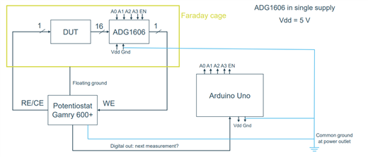
In terms of grounding and removing noise, I use a faraday cage with the floating ground of the potentiostat connected to it. I also use the same earth ground for the ground of the potentiostat, arduino and multiplexer. 
A block schematic for my setup: 
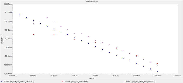
That is why I started to look into the MUX36S16 because it only has a 1pA leakage current. Unfortunately, I still do not get the same impedance spectra with/without this multiplexer. Below are my measurements:

- Blue: measurement without mux
- Red: measurement with mux
- Purple: measuring the impedance of just the mux, but without the device connected (open channel).  To test the limit of which values can be measured with the mux connected to the potentiostat.
Is this mux also not suitable? Although looking at the values of the measurement of the open channel (just the mux = purple), these values surpass the values of the impedance of my channel, meaning that the leakage current would not limit the measurement I suppose?  Do I need to ground all the S channels I do not use to limit stray capacitance or? Any ideas on things I could try to limit the leakage currents/noise on the measurement with the mux?

Kind regards
  • Hey Laurens, 

    Are your traces gaurded? Typically for higher precision applications adding some gaurding rings around your traces will help reduce parasitics from the board itself. So like board resistance between your traces any stray capacitances. Your cage should remove any extra noise though but gaurding can help with that as well. 

    You'd want to bias your guard ring to the voltage of the signal.

    We have a application note that goes in a lot more details on this here : 

    Guarding in Multiplexer Applications

    I also just want to make sure I'm clear on the understanding here. The graph's x-coordinates aren't terrible visibly clear here but am I right to assume that 1,000MHz is supposed to be 1MHz and not 1000MHz (1GHZ)?

    Although looking at the values of the measurement of the open channel (just the mux = purple), these values surpass the values of the impedance of my channel, meaning that the leakage current would not limit the measurement I suppose? 

    I agree with you on this point but just wanted to dig a little more into how we're interpreting your results. So blue is DUT, no mux; Red is DUT + MUX; Purple is mux no DUT?
    From your description for the purple use case, it sounds like you're floating the input (open channel) when you remove the DUT. Would you get a more accurate reading if you shorted the path where the DUT/MUX would have been?

    Either way, you may want to give gaurd rings a shot to help minimize leakage.


    Thanks,
    Rami

  • Indeed, I want to measure the frequency spectrum between 1 Hz and 1 MHz.

    I found that note about guarding, but how can I bias the guard ring the the voltage of the signal? Do I need some other components like a buffer and opamp for this? For now, I just soldered the mux on a prototyping board and connected the relevant signals with jumper wires. That is also how I connect my sample to the relevant cables of the potentiostat. The thing is that my voltage signal changes between channels and over time, so how can i accurately follow the signal voltage and use it as a bias? A source follower?

    So blue is DUT, no mux; Red is DUT + MUX; Purple is mux no DUT?

    This is correct.

    I can try to short that path, but for now I just left the crocodile clamp for the working electrode not attached to anything and the same for the reference electrode of the potentiostat. In any case, I just need my signal to be the same when just measuring the DUT and using the mux connected to the DUT.

    Thanks for the help.

  • Hey Laurens,

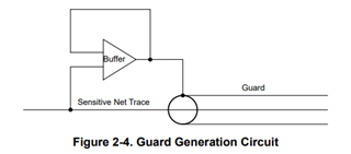
    Yes, you'll need to add some external circuitry for the gaurding circuit. This is from that app note I linked above : 

    So you will need to add a buffer for more precise applications.

    -Rami

  • Hi Rami

    Is there anyway I can test this already without making a PCB with these mux integrated on. For now, I just used this prototype board https://www.hobbyelectronica.nl/product/pcb-voor-soic-28-tssop-28/ where i soldered them on. 

    Also, would it make a lot of difference using the SOIC compared to the TTSOP in this regard?

    Should I also go to another type of mux like the TMUX1108. In the datasheet of the MUX36S16 it says 1pA leakage current, but on another forum post I found that the actual leakage current would be ID(ON)+15* ID(off), this would correspond to 10pA +15* 10pA = 160 pA for the MUX36S16, while only 3pA+15*10pA for the TMUX variant.

    If I would then ground the pins that are not being used during the measurement I could get only 10pA for the MUX36S16, while 3pA for the TMUX. Is this reasoning correct?

    Because 160pA with a high impedance source ( like 5 Mohm for my test sample) this could lead to 10pA*5Mohm = 50mV. For a potentiostat using 100mV, this would lead to a too large error voltage I think?

     Kind regards

  • Hey Laurens,

    For starters, I want to clarify the Leakage specification. The On-Leakage incorporates the Off-Leakage. When we measure the on-leakage, the off-leakage is still there on the drain so we can't really isolate them. So you'd actually just be relying on the actual ID(ON) spec alone and not add the extra ID(OFF) per channel like you're doing. So really we'd be comparing MUX36 10pA to TMUX 3pA. And the error would mathematically still be at the 50mV for the MUX36 device.

    Grounding your unused pins may help slightly but I don't think the impact would be significant. Although it seems like a pretty easy thing for you to do on the board to test quickly so it wouldn't hurt to give it a shot, but I don't anticipate it to help a significant amount.

    Another thing that you may also need to take into consideration is the leakage affects at different frequencies. Typically the leakage is done at DC. At AC the parasitics play some role. So the capacitance may charge/discharge and inject current back in, which would be difficult to quantify the actual affects. Can you run some DC tests and see how well you're matching up? I know 1Hz is already pretty close but let's check a baseline first at actual DC.  

    Unfortunately it will be hard to get decent AC, high precision results with something like the board that you linked though. These breakout boards are made more for DC testing. There really isn't any consideration for matching or leakage here since it isn't the intended purpose. 

    -Rami

  • Hi Rami

    Thanks for the clear answer. I found that calculation on another forum post about the mux. I know it involves a lot of guessing, but in your experience, do you think I could get the error voltage in the order of a couple of mV when designing my own pcb with the guard and box rings and putting the mux on there? Wouldn't it in any case make a lot of difference to go for the TMUX as the leakage current is still 3 times smalles as well as going for a SOIC variant?

    Kind regards

  • Hey Laurens,

    I'm not sure if switching muxes will be as advantageous as focusing on the layout. When you get to the low pA range for precision it's going to be a layout investment you'll need to make. Of course some of the leakage is mux related (and truthfully your leakage is a bit AC off-iso plus DC leakage) but the board will be the biggest factor. So while I can't guarantee that you'll meet your mV error goal I do think that those changes will help get you at least closer to what you currently have. I worry that any gain from changing the device will be hidden by the noise that the board itself would have. 

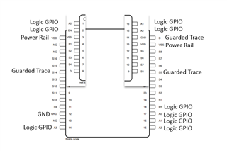
    I would definitely recommend testing it in person with a prototype before finalizing a full board. I gave it some thought and I think you'll be able to test a single channel of both the TMUX1108 and the MUX36S16 Using a single layout and switching out the devices using an extended PW footprint like below: 


    Functionality would change depending on the device that is soldered on. This would atleast let you compare the TMUX1108 and MUX36 results using the same layout. 

    I hope that made sense but I can help clarify if not. I know the image isn't the best. But for example, when you have the TMUX1108 soldered down, pad3 would be VSS and pad29 would be VDD and you would solder the mux in the very top of the footprint.
    When you have the MUX36 device you would solder pin 1 on pad 3. Then your pad 3 would be VDD and pad 29 would be VDD. 


    Thanks,
    Rami